Strip Web Options and Results
Define a carrier web type and place it in the strip layout.
Carrier Web definition is a critical step in the strip layout process when creating the sketch for the carrier. It will be a contributing factor to the blank orientation, overall material consumption, and blank stability during the strip progression process.
Webs commonly have two different types of attachments.
-
Carrier to Blank - A web attaches the blank being formed to the steel coil or strip.
-
Blank to Blank – A web attaches the blanks together to stabilize the progression movement process ('Part to Part').
The web attachment selection is based on a variety of criteria and functions, such as the need for extra pilots, stabilizing blank/part during the progression movement (minimizing bounce), predicted blank pull in during forming, and ease of trimming.
Carrier Webs can also be put into two general types, fixed or stretch.
-
Fixed webs form a rigid connection between its attachment points.
-
Stretch webs form a flexible connection between its attachment points.
Note: This function is enabled only when the strip design environment is activated.
Required Step 1 
-
Click the point on the part where the web will attach. The following settings are displayed:
Value
Description
No Copy
By default, geometry will not be copied. Click the option to select one of the following options:
- Copy Forward
- Copy Backward
- Copy Forward and Backward
-
Select the type of web to be inserted. The options are illustrated in the dialog.
Web Type
Type
Image
Specific Configuration Options
Solid
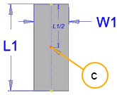
C = Insertion and Rotation Point
W1 = Set the Web Width
L1 = Set the Web Length
Flip Direction is unavailable
Minimum Distance is unavailable
L-stretch
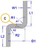
Two modes are available―Standard and Advanced.
- In Standard mode, some settings are automatically configured.
- In Advanced mode, you must configure all values.
Value
Standard Mode
Advanced Mode
C Insertion and Rotation Point W1
Web Width L1
Web Length O1
Offset
R1
Bend Radius 1 L1
Attach Length 1 A1 Web Angle (90° default) R2
R2 = R1
Bend Radius 2
L2
L1 = L2
Attach Length 2
C-stretch
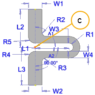
Two modes are available―Standard and Advanced.
- In Standard mode, some settings are automatically configured.
- In Advanced mode, you must configure all values.
Value
Standard Mode
Advanced Mode
C Insertion and Rotation Point W1
Web Width
W2
W2 = W1
Web Width
W3
Expansion Width = 2 x R1
W4
Web width in the C section
L1
Web Length
O1
Offset
R1
Bend Radius 1
L1
Attach Length 1
A1
Web Angle (90° default)
R2
Bend Radius 2 to C section
R3
R3 = R2
Bend Radius 3 to C section
R4
R4 = R2
Bend Radius 4 to C section
R5
R5 = R2
Bend Radius 5 to C section
L2
Web Length 2 to C section
L3
L3 = L2
Web Length 3 to C section
Oval-stretch
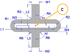
Two modes are available―Standard and Advanced.
- In Standard mode, some settings are automatically configured.
- In Advanced mode, you must configure all values.
Standard Mode
Advanced Mode
C Insertion and Rotation Point W1
Web Width 1 to oval section Web Width 1 to oval section W2 W2 = W1 Web Width 2 to oval section W3 W3 = 2 x R1 W4 Web Width 4 of oval section L1
Web Length O1
Offset
R1
Bend Radius 1 L1
Attach Length 1 A1 Web Angle 1 (90° default) Web Angle 1 (90° default) A2 A2 = A1 Attach Length 2 R2
R2 = R1
Bend Radius 2
R3 Bend Radius 3 to oval Section Bend Radius 3 R4 R4 = R3 Bend Radius 4 R5 R5 = R3 Bend Radius 5 R6 R6 = R3 Bend Radius 6 L2
Attach Length 2 L3 L3 = L2 Attach Length 3 Template
The web geometry can be saved as a template and retrieved for subsequent web configurations.
Connection Type
Select the connection type:
- Carrier to Blank - Web attaches the blank being formed to the steel coil or strip.
- Blank to Blank – Web attaches the blanks together to stabilize the progression movement process ('Part to Part').
Symmetric Strip
Stitch to Strip
Flip Direction
Mirror the web geometry of an L-stretch web or a C-stretch web about the Y-Axis passing through the Insertion and Rotation Point.
Minimum Distance
The minimum reference distance from the expanding region of the web to the blank or carrier attachment point (stretch web types only).
Rotation
Use the slider to set the rotation angle of the web around the Insertion and Rotation Point