Tool Trajectory Parameters: Turning  > Thread
  - Thread Tab
Create a thread on the outside or inside diameter of the turning material.
Used for lathe threading.
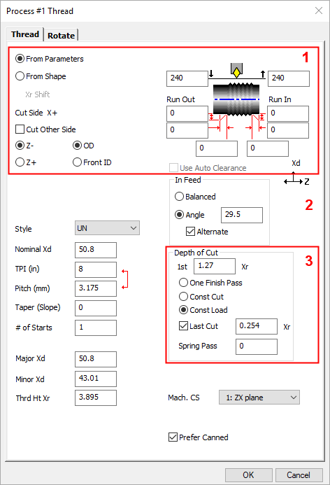
The Tool Trajectory parameters for Turning > Thread are displayed in a dialog. The Thread tab is displayed below.
|
|
See also: |
Thread Cut Options |
||||
|
|
These checkboxes indicate the direction the tool will move along the designated cut shape. |
|||
|
From Parameters |
From Parameters lets you specify values for taper and for Xd (nominal, major, and minor), and it allows you to choose to use canned cycles option if your turning machine supports them. |
|||
|
From Shape |
From Shape is especially useful for bone screws, where you want to create a thread along a general shape that might include several connected lines, arcs, and splines. If this option is selected, the Xr Shift parameter becomes available. |
|||
|
Xr Shift |
Xr Shift follows the up/down
direction of Xd; for an OD, a negative value shifts inward, and for an
ID, a positive value shifts outward. |
|||
|
Cut Side X+ |
Cut Side tells you which side (usually X+ or X-) will be cut. To flip the positioning, select or deselect the Cut Other Side checkbox. |
|||
|
Cut Other Side |
||||
|
Z- |
Define the machining cut direction. The selection made for the cut direction option determines the direction the tool will move when creating the thread; Z- will cut toward the spindle and Z+ will cut away from the spindle. The Z- choice is the default as most threads will be cut toward the spindle; only in rare cases is the Z+ option used. The Run In and Run Out distances and the actual thread start and end will change positions in the Clearance/Thread Diagram depending on the cut selection. |
|||
|
Z+ |
||||
|
Approach/Retract Type |
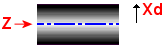
The Approach/Retract Type selection designates the axis along which the tool will approach and retract from the part. These are similar for all Turning procedures, with the exception of Lathe Drill. On most turning machines, X is radial and Z is axial, as shown below.
The OD (Outside
Diameter of the part) and Front ID (Front
Inside Diameter
of the part) approach type options specify that the tool approaches and
retracts radially along the X axis, on most turning machines. Once the Approach Type is selected, the corresponding Clearance diagram appears in the Process dialog. The boxes with the arrows next to them represent the Entry and Exit Clearance Positions that the tool may use when approaching and retracting from the part; both boxes are labeled with arrows going towards and away from the part, respectively. The Entry and Exit Clearance Positions are only required when Auto Clearance is turned OFF. Entry Clearance Diameter/Radius
specifies the location to which the tool will make a rapid move, before
it begins to feed radially to the operation's start point.
Exit Clearance Diameter/Radius
specifies the location to which the tool will make a rapid move, after
it has completed cutting at the operation's end point.
For the Thread procedure, only the OD and Front ID approach selections are available. With both selections in the threading process, the approach is along the X axis. These selections allow you to determine whether the thread will be located on the OD or the Front ID of the part. This is used to specify whether you are cutting an external or internal thread; the type of thread will affect the approach moves to the thread cutting cycle. It is also correct to think of this as the Thread Type. |
|||
|
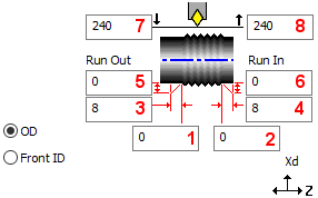
OD |
The OD approach type option deploys the toolpath on the Outer Diameter of the part. For this option, the following Clearance Diagram is displayed:
The Thread Clearance diagram is also used to define where to cut the thread.
Thread Start Z: This value is
used to specify where the actual thread begins in Z. Note that this is
not the Z start of the thread cycle.
Thread End Z: This value is
used to specify where the thread ends in Z.
Run In / Run Out: A run-in acceleration
distance is typically used to allow the spindle to come up to speed before
threading occurs.
Z Run In: Specifies the acceleration
distance in Z, incrementally. For example, if the thread cycle is to start
300/1000" before the actual thread start, simply enter 0.3 for Z
Run In.
X Run In: Specifies the acceleration
distance in X, incrementally, if necessary. The value is normally zero,
and almost never larger than the value for Z Run In.
Z Run Out: This value will extend
the thread by the amount entered. If the threading tool needs to pull
out from the thread on an angle, enter a value for both Z Run Out and
X Run Out. Typically, you would enter 0.
X Run Out: When used with Z Run Out, will cause the tool to pull out of the thread on an angle. Example. To specify a thread pull out of 100/1000" at 45 degrees, enter 0.707 for X Run Out and 0.707 for Z Run Out; this would cause a pull-out move at 45 degrees for a distance of 0.100 to be added to the thread cycle. If the value for X Run Out is less than for Z Run Out, a pull out move of less than 45 degrees will occur; or, if the value for X Run Out is larger than for Z Run Out, a pull out move greater than 45 degrees will occur. Entry Clearance Diameter/Radius
specifies the location to which the tool will make a rapid move, before
it begins to feed radially to the operation's start point.
Exit Clearance Diameter/Radius
specifies the location to which the tool will make a rapid move, after
it has completed cutting at the operation's end point.
|
|||
|
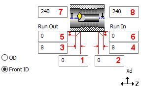
Front ID |
The Front ID approach type option deploys the toolpath on the Front Inner Diameter of the part. For this option, the following Clearance Diagram is displayed:
For parameter explanations, see OD above. |
|||
|
Auto Clearance |
Specify whether the clearance positions are to be calculated automatically
by the system or are fixed positions based on a user-defined part clearance
position. The Auto Clearance option performs several functions when it is turned on. It will calculate the part clearances in both Z and X that are used to position the tool between each operation. These positioning moves will be dynamically calculated for each operation. This means that as the stock conditions of the part change as material is removed, the clearance positions will adjust accordingly. When Auto Clearance is ON, the system will also take into account where the tool needs to be to begin the next operations' toolpath when calculating the positioning moves. Additionally, the Auto Clearance function may add entry and/or exit moves to the toolpath in order to safely maneuver around the part. The Auto Clearance function generates the most efficient positioning moves around a part. However, canned cycles cannot be used in conjunction with Auto Clearance. In order to use canned cycles, which are turned on in Process (Tool Trajectory) dialogs by selecting the Prefer Canned option, Fixed Clearance positions must be used. The Auto Clearance option requires the user to enter an offset amount from the part stock that the system uses to calculate the clearance positioning moves between operations. Because the stock conditions are constantly changing as material is removed from the part, in order to optimize the toolpaths, an offset amount is used for positioning rather than absolute positions. Fixed clearance, which is used when Auto Clearance is turned off, uses absolute positions. When this option is OFF,
fixed clearance positions are used by the system to calculate clearance
moves. In this case, you need to enter an overall part clearance in the
Clearance
& UCS Motion Parameters (in the Xr/Xd
and Z text boxes), as well as
Entry and Exit Clearance Positions in the Process dialogs for each operation.
When using canned cycles, fixed clearance positioning should be used. When the Auto Clearance option is turned OFF, fixed clearance positions are used by the system to calculate clearance moves. The user must enter an overall part clearance in the Clearance & UCS Motion Parameters, as well as Entry and Exit Clearance Positions in the Process dialogs for each operation. When using canned cycles, fixed clearance positioning should be used. The overall part clearance is entered in the Clearance & UCS parameters in the Xr/Xd and Z text boxes that become active when Auto Clearance is turned off. They designate the position the tool will rapid to and from during a tool change. This position will also be used when moving from one approach type to another between operations that use the same tool. The absolute positions specified in the Xr/Xd and Z text boxes are locations the tool can rapid to when moving around the part. One or both of these fixed positions are used whenever a tool is moving to the start point of the toolpath or exiting from the toolpath. Where the tool moves when approaching and retracting from the part depends on the Approach Type selected and the positions specified in the Clearance Diagrams in the Process dialog.
|
|||
|
|
||||
Thread Definition |
||||
|
|
Set the thread definition parameters. |
|||
|
Style |
This dropdown menu is used to select the thread style, such as UNF,
NPT, etc. |
|||
|
Nominal Xd |
This is the nominal thread diameter. |
|||
|
TPI |
This is the number of threads per inch, (per millimeter for metric parts). |
|||
|
Pitch |
TPI and Pitch are interactive inputs. Entering either the TPI or Pitch calculates the value for the other input. For example, entering a TPI value of 1.0 will calculate a Pitch value of 25.4 (and vice versa). |
|||
|
Taper (Slope) |
Taper is a "slope" value, not an angle. A slope is a ratio
of vertical/horizontal distances. The equivalent angle is: This is the decimal slope of the thread taper, measured radially. For straight threads, this value should be zero. The NPT specification defines the taper as 1/16, or 1" vertical for 16" horizontal, with the horizontal measured on the diameter, which is 1/32 of an inch per inch radially. As this entry requires a radial slope (or 1/32), you may type in 1/32 or you may type in .03125, the decimal equivalent. If your taper is defined as a radial angle, the slope = arctan (angle). If you are creating a tapered thread with Run In, Canned Cycles should not be used. This is because most machines cannot handle this situation. |
|||
|
# of Starts |
This is the number of thread starts. Most standard threads have one
start. |
|||
|
Major Xd |
The value in this text box automatically defaults to the value entered
for the Nominal Xd; however, it can be changed. Cutting begins at this
diameter on an OD thread. |
|||
|
Minor Xd |
The value in this text box defaults to a calculated value based on the Nominal Xd and the desired pitch. Cutting begins at this diameter on an ID thread. Major/Minor Xd Note: These values will default to the theoretical major and minor diameters based on a perfect sharp thread. The value as calculated is primarily for reference; this value can be changed as required for the particular thread class and fit desired. For OD threads, the minor diameter is critical as this will be the diameter that the tool will cut on the finish pass. On ID threads, the opposite is true. The major diameter is critical as this will be the diameter that the tool will cut on the finish pass of an ID thread. |
|||
|
Thrd Ht Xr |
This value is the actual thread height as a radius dimension. This value is calculated as the radial difference between the Major Xd and the Minor Xd diameters and dividing it by two. This value can be changed as required. |
|||
|
|
||||
|
In Feed |
This section allows you to control how a threading insert will cut. |
|||
|
Balanced |
This choice will feed the thread tool straight in for each pass resulting in both edges of the thread tool cutting equally (the Balanced option will cut with both sides of the insert equally). For UN thread forms, a Balanced or 0° In Feed takes all cuts at the same Z position. Note: The Balanced In feed is often used when cutting tough stainless steels that are easily work hardened, as the equal metal removal method helps prevent work hardening during the cutting cycle. This method usually does not work well on softer materials that tend to load up on the insert; for these materials it is usually best to use the Thread Angle In feed. |
|||
|
Angle |
The Thread Angle selection allows you to specify the In Feed angle. The value entered is measured in degrees and specifies the single edge In Feed angle for the thread form. The value 29.5° is the default Thread Angle for all thread types. Each cut starts at a different Z position, always cutting with one edge. This choice will cause the positioning move at the start of each pass to feed the thread tool in at the angle specified, resulting in the leading edge of the tool doing most or all of the cutting. It is common to set the in feed angle slightly steeper than the thread angle so that the trailing edge of the tool takes a ‘light’ cut to ensure that the back side of the thread cleans up. Note: This option is often used to improve the chip flow on soft materials that tend to tear during the cutting cycle because of material load up on the tool. |
|||
|
Alternate |
The Alternate option is available when Angle is the In Feed selection. When this option is ON,, it will alternate the in feed, resulting in the tool first cutting with the leading edge, then alternating to the trailing edge, and then back to the leading edge, etc. (e.g. 29.5°, -29.5°, 29.5°). Only one edge is used at a time to cut, but it alternates to provide even tool wear, in turn providing maximum insert life. This is also known as "using the leading edge & trailing edge alternately". |
|||
|
|
||||
|
Machining CS |
If your part has multiple UCSs, select the coordinate system to be used for this operation, from the dropdown list. The system will output the appropriate rotation moves to correctly position the part to cut using the selected UCS. The tool always approaches the part and cuts along the positive depth axis of the selected machining coordinate system. |
|||
|
Prefer Canned |
When this checkbox is ON |
|||
|
|
||||
Thread Depth of Cut |
||||
|
|
The values and options in this section of the Thread dialog are used to control the number of cuts as well as depths of cuts, minimum cut depth, and spring passes. |
|||
|
1st <Const. Cut / Const. Load value> Xr |
This value is the stock amount to remove on the first rough pass. This value also controls the entire roughing cycle as described below for Constant Cut and Constant Load. |
|||
|
One Finish Pass |
The One Finish Pass option specifies that the tool will make a single
pass over the thread at the finish thread depth. Its primary use is to
re-cut an existing thread to remove burrs or small excesses of material. |
|||
|
Const. Cut |
The Const. Cut selection allows the user to designate the depth of the
cut that the threading tool will make on each pass. The value is measured
as a radius and is entered in the text box labeled 1st. |
|||
|
Const. Load |
The Const. Load option is the most commonly used type of thread roughing
cycle. |
|||
|
Last Cut |
When this option is ON, this option will prevent any cut from removing less than the given amount of material on the last pass. The value entered is measured as a radius value and specifies the minimum cut to which the constant load will diminish. The rough cycle will always leave exactly this amount for the last pass. |
|||
|
Spring Pass |
The Spring Pass option can be used in conjunction with any of the depth of cut selections. It will create additional passes (at the finish depth) equal to the number entered after the thread has been cut. |
|||
|
|
||||