Cutting Conditions
In this step the material and wire to cut the part must be selected.
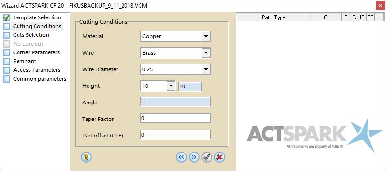
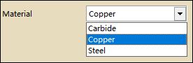
The first thing to do is define the part material. Only the available materials will be shown in the pull-down menu.
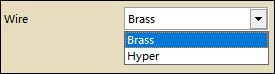
Next you will find the wire type selection. Only the available wires for the part material will be shown.
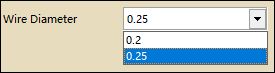
The next step consists in selecting the wire diameter. You can choose between the diameters displayed in the pull-down menu (only the available diameters for the chosen material will be shown). In this example:
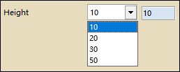
Next, the thickness is shown. The thickness is taken from the part definition.
Notice that two different thickness are displayed. The right-side thickness field is the real value of the part thickness and the left-side thickness is the one found in the Database.
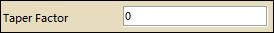
You can set a Taper Factor.
Part offset (CLE) allows you to modify geometrical CLE from the processes wizard.
When wizard is showed at first, this field contains the current geometrical value.
It is only available when we haven't applied more processes or wizards over the geometry and, in case of having multiple node selection, all the geometries have the same value.
