|
|
Add Wedge  : Local Wedge > Normal


Access: Open this function from one of the following locations:
-
Select Mold Design > Insert > Add Wedge from the menu bar.
-
Select Die Design > Insert Tools > Add Wedge from the menu bar.
-
Select Insert > Add Wedge from the Mold Design Guide or Die Tool Design Guide (DieDesign).
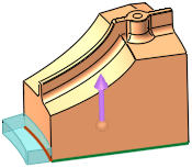
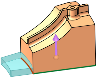
Add a wedge to a solid object to lock it in position. A cutting object can also be selected.
|
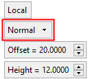
Offset |
This parameter is only displayed if the Extend or Normal options are selected. Define the offset from the picked edge(s).
Valid values: ≥ 0. |
||||||
|
Height |
Set the height of the wedge. This parameter appears for all Global and Local options; the example below is for a Local wedge.
|
Screen Parameters
When the Normal option is selected, the following additional screen parameters are displayed at the ends of the selected edge(s):
|
|
|
|
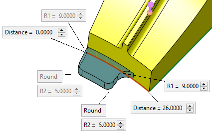
Normal: One Edge - Round |
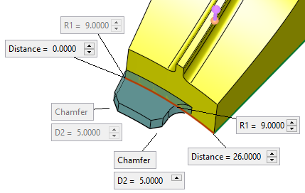
Normal One Edge - Chamfer |
|
|
|
Normal: Two Edges - Chamfer |
Normal option screen parameters:
|
Distance |
The distance between the end point of the selected edge(s) and the start of the wedge. This is shown in the image below as the "X" value. This parameter appears, and can be set, at each end of the selected edge(s) to which the wedge is to be added. |
|
Round / Chamfer |
This is a toggle option Round / Chamfer to define the shape of the wedge. |
|
R1 |
These parameters appear at each end of the wedge. R1 is the radius of the wedge where it meets the selected edge(s). R2 or D2 is displayed depending on the selected toggle option: Round / Chamfer. These parameter values can be defined only at one end of the wedge and are reflected at the corresponding grayed out R1/R2/D2 parameters at the other end of the selected edge. |
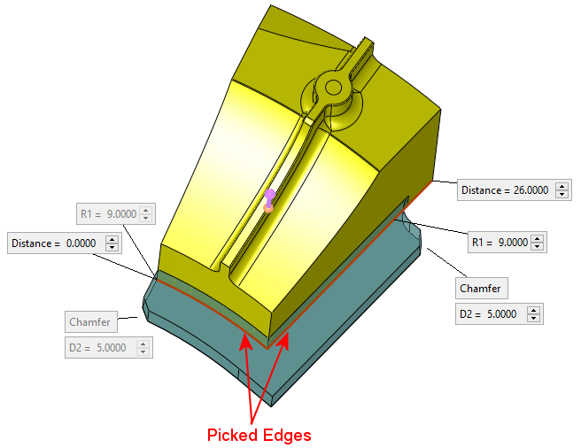
Normal option parameter examples:
|
In the example below, 3 edges are selected: |
A wedge is added to the selected edges: |
|
|
|
| The additional screen parameters are displayed at the ends of the selected edges (the "X" refers to the Distance parameter): | |
 |
|
|