Automatic Coordinate Table  : Editing

Access: Open this function from one of the following locations:
-
Click the
button in the toolbar. -
Select Symbols > Automatic Symbols > Automatic Coordinate Table from the menu bar.
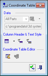
Edit a Coordinate Table. The editing dialog for the Coordinate Table is displayed.
Edit a Coordinate Table
-
InvokeInvoke the editing dialog for the Automatic Coordinate Table function.
The editing dialog for the Coordinate Table is displayed:
This dialog is similar to that displayed for the BOM.
- Press the Edit Coordinate Table button
 . The Coordinate Table Editor dialog is displayed.
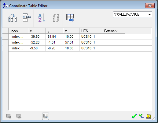
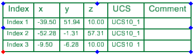
To enter text in the columns, double-click in the columns.
For additional information, see:
- Dialog Buttons
- BOM: Editing Operations
- BOM: Dynamic Editing - Drag and Drop Operations
- Automatic Coordinate Table: Report
Coordinate Table Editor Dialog Buttons
A similar dialog is displayed when editing the Assembly BOM Table, Drafting BOM Table and the Drafting Coordinate Table. The buttons below are common to each of these tables. Each of these tables has additional button(s) which are described in the relevant topic.
Buttons Common to All BOM Dialogs
|
|
Select Columns: Select which columns will appear in the table as well as their order, and create new columns. The properties of individual columns (such as name, width, and text justification - left, center, right) can also be defined. Note: Column widths can also be set dynamically from the BOM Table Editor dialog or from the BOM Table in the Drafting Sheet. In both these areas, drag the appropriate column walls to the required width. The Column Chooser dialog is displayed. |
||||
|
|
Add Row: Add rows to the table. |
||||
|
|
Sort BOM/Coordinate table: Sort the table according to field entries. The Sort TableSort Table dialog is displayed.
To sort the BOM fields:
The BOM is sorted appropriately. The BOM before sorting:The BOM before sorting:
The BOM after sorting:The BOM after sorting:
Press OK to update the BOM table in the Drafting Sheet.
|
||||
|
|
Renumber: Renumber the table entries, based on the current display, from 1 onwards. The difference between Renumber and Sort is that Renumber retains the current appearance, but just changes the numbering of the table entries. The examples below are for the BoM but are also relevant for the Coordinate Table. The BOM before renumbering:The BOM before renumbering:
The BOM after renumbering:The BOM after renumbering:
A Preference option blocks the reuse of ID numbers of deleted items. When selected, this means that only new ID numbers are assigned, instead of overwriting the ID numbers of deleted parts. |
||||
|
|
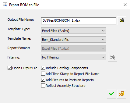
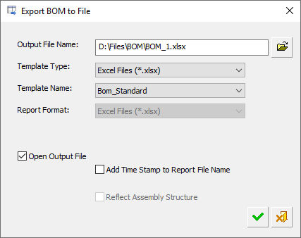
Export BOM to File/Coordinate table to file: In all cases, this displays the Export BOM to File dialog to save the relevant table as a file in the requested format. The Export BOM to File dialog differs slightly in the Assembly and Drafting environments. The Export BOM to File dialog is displayed.
See the BOM Report for additional information. |
||||
|
|
Save as BOM Template: Save the BoM template as an XML file. BTP File (*.btp) This file can then be retrieved (Set BoM Template - below), and used as a template for other BoMs. The Save as BOM TemplateSave as BOM Template Template dialog is displayed.
The BOM templates are saved as .btp files in the folder: |
||||
|
|
Set BOM Template: Retrieve a previously defined BoM template file (.btp) (Save as BoM Template - above), and use it for other BoMs. The Set BOM TemplateSet BOM Template dialog is displayed, select the required template.
The BoM templates are saved as .btp files in the folder: |
In the Drafting environment, the following additional button is available in the Table Editor:
|
|
Reconnect to Model: Synchronize the Drafting BOM with the Assembly BOM. This button also appears in the ID Number dialog. |
