Cut Manager

Access: The Cut Manager dialog is displayed in a number of functions (as one of the steps), for example:
Assembly functions: For example, in Add Component, Add Duplicate, Add From Catalog, Assembly Mirror.
MoldDesign functions: For example, in Cooling Objects and Cooling Cut.
Select the parts to be cut by defining them in the displayed Cut Manager dialog. All components used in the cut operation that have a cutting object, are represented in a tree adjacent to the Cut Manager. This option is used to manually control which parts are to be cut.
Cimatron speeds up tool design by automatically creating pockets for added parts (such as screws, inserts, lifters, and ejectors). The Cut Manager provides full control over this process, letting you override automatic settings and decide exactly where to cut; This removes obstacles arising from when automatic processes do not provide exactly what is required. The Cut Manager is effective for added sub-assemblies (such as sliders) as well.
The Cut Manager dialog is displayed—the dialog displayed in the Assembly and Mold Design (when a cooling item is selected) environments has slight variations:
|
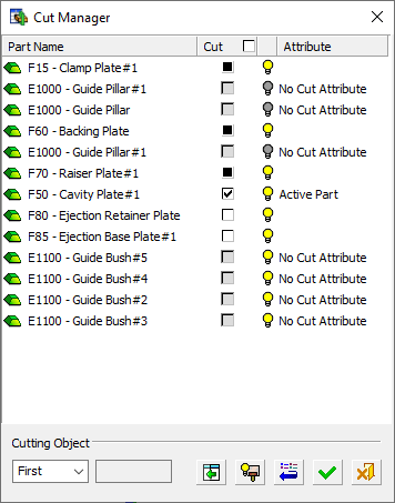
Cut Manager in Assembly |
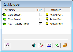
Cut Manager in Mold Design (when a cooling item is selected) |
|
|
|
In This Section
Usage Example
|
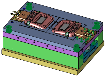
Example assembly with some components selected to cut other components. |
The Cut Manager displays the components affected by this operation and offers full control over which parts to cut. |
|
|
|
|
Expand ( Click an item on the tree to highlight it in the graphics pane or click an item in the graphics pane to highlight it in the tree. The tree pane displays hide/show and render transparency icons adjacent to each component, which can be used to enhance visualization. |
|
|
|
|
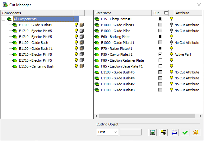
When there is more than one parent (multiple assemblies, assemblies and parts, multiple parts, and so on), an entity called All Components is displayed as the head of the tree, as shown above. When a single assembly is the parent of all the components with cutting objects, it appears as the head or root of the tree, as shown below.
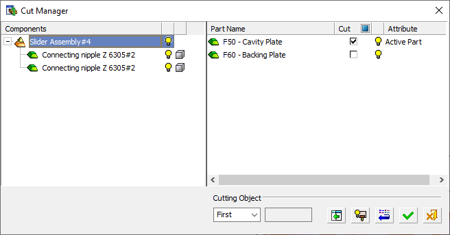
Click an item in the tree (in the left pane of the dialog) to display the cut manager settings for it (in the right hand pane).
Dialog components
|
Part Name |
The list of parts that should be cut, according to the cut analysis results. In addition, this includes:
No hierarchy is considered when analyzing intersected parts; parts from all over the assembly are included in the analysis. The cut analysis is performed each time the optional step is entered. This means that any changes made in previous steps is analyzed. |
||||||||
|
Cut |
The Cut checkbox appears in the column header as a global ON/OFF switch to select or clear all items, respectively. The Cut checkbox also appears for each row of the Cut Manager table and displays the cut analysis results as follows:
|
||||||||
|
Hide |
All parts appearing in the dialog are shown by default. Control the display of these parts by using the Hide |
||||||||
|
Attribute |
The Part attribute. |
||||||||
|
Cutting Object |
A dropdown list containing the cutting objects in a Part or an Assembly. You can handle cutting objects by selecting them from the dropdown list. Changes made to the indications and hide/show status are reflected in the dialog and in the graphics area. The dropdown list is populated according to the number of cutting objects in the Part or Assembly. Part For example; if a part has two cutting objects, then All, First, and Second are the options; if it has four cutting objects, then All, First, Second, Third, and Fourth are listed. The dropdown list is dimmed if only one cutting object exists in the Part Name column. In this case, First is displayed from the dropdown list. Assembly |


Dialog buttons
|
Assembly Cut Manager buttons |
|||||
|
|
Expand/Collapse Tree Pane Expand or collapse a tree display showing all components used in the cut operation that have a cutting object. When there are multiple items (including instances) with cutting objects, this button becomes available. If there is only one component with a cutting object, this button is not available. |
||||
|
|
Hide/Show Cutting Objects Hide or show the cutting objects of all cutting parts. This is an on/off switch. The default for the cutting objects is shown (therefore the Hide button is displayed |
||||
|
MoldDesign Cut Manager buttons |
|||||
|
|
Filter Components Filter the components to exclude unnecessary components such as screws, bushings, cooling items and so on, from the cut list. A Selection Filter dialog is displayed.
|
||||
|
|
Hide/Show Cooling Objects Hide or show the cooling objects. This is an on/off switch. The default for the cooling objects is shown (therefore the Hide button is displayed
|
||||
|
|
Recalculate Invoke a new cutting analysis. Recalculate the components to be cut by the cooling channel. This is used in cases where, for example, you added a component after the cooling object was created, and you want the cooling object to cut this new component as well. This option will recalculate the cutting list. |
||||
|
Common Cut Manager buttons |
|||||
|
|
Reset: Reset all values and settings to the system defaults. |
||||
|
|
OK: Accept the changes, perform the operation, and close the current dialog/task. |
||||
|
|
Cancel: Cancel all changes and close the dialog/task without saving the settings. |
||||
Using Cut Manager
If required, override the analysis results by selecting the checkbox for the appropriate cutting object. The following rules apply:
-
When checking a partially cut component (
 ), it becomes a fully cut component (
 )
) -
When checking a cut by none component (
 ), it becomes a fully cut component ()
 -
When checking a fully cut component (
), it becomes a cut by none component ()
Click the ![]() button to restore the original analysis results. This cancels any changes made to checkboxes.
button to restore the original analysis results. This cancels any changes made to checkboxes.
The rows displayed in the dialog can be sorted in ascending or descending order, according to Part Name or Attribute, by clicking on these column titles.
Selecting a row in the table also highlights the appropriate component in the graphics pane, unless it is marked as hidden.
This optional step is displayed;
-
If the component being added has a cutting object (or, if multiple components are added, if at least some of the added components have cutting objects).
-
If the With Cut option is used.
-
After completing all the Required Steps of the function.