Assembly

Managing Cuts

Transfer attributes with Assembly Cut Picture 43

The ‘Assembly Cut by Selection’ function is the assembly equivalent of a manual Solid / Cut operation. Parts in assembly are cut by the selection of other parts. Like Solid / Cut, Assembly Cut by Selection can now transfer attributes.

  • Examples of attributes transferred into the part being cut are face colors, threads, and manufacturing attributes.

  • Editing an assembly cut offers the ability to update transferred attributes based on any new conditions.

Transfer Attributes is a new option in the assembly cut by selection function.

Color and manufacturing attributes are important non-geometric data that can be transferred during an assembly cut procedure.

Improved Cut Manager response time Picture 44

The Cut Manager is a useful option that runs a contact analysis between the parts being added and the full assembly. It creates a list of parts that can receive specific pocketing instructions and changes the display. While both actions are important, in a large assembly they can take time. Cimatron 2026 adds a new Modeling preference for improved Cut Manager performance.

A new option in the Preferences allows the system to ignore parts that are assigned the No Cut attribute. This is a common attribute on screw, pins, baffles, and many other standard parts.

The new option is in a new page called Cut Management under the Modeling branch. It is called Show parts that cannot be cut in the Cut Manager Window. By default it is turned off. When turned off, parts with the No Cut attribute will skip the contact analysis and will no longer be listed or displayed in the Cut Manager.

In many large assemblies, this will drastically improve the Cut Manager response time.

The new preference is not enabled by default for improved Cut Manager performance.

The Cut manager list in previous versions could be showing many parts that are unable to receive cut features.

Cimatron 2026 can provide a more concise list of parts, for
quicker and easier changes in cut status.

Logical Cut Manager order Picture 45

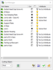
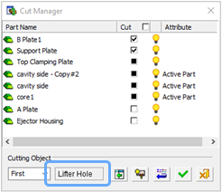
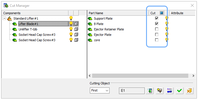
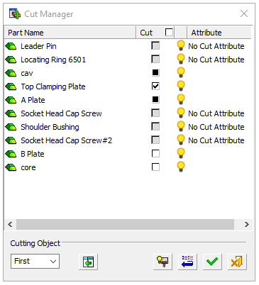
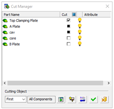
In prior versions the Cut Manager contact analysis would list all the parts in a somewhat random order. For Cimatron 2026 some rules have been developed to consistently structure the list. The order of the list is based upon the default cut status of the first cutting object in the added parts. This makes finding the parts that need a cutting adjustment an easier process.

  • The first component listed will be the one supplying the face, cone face, or UCS being used to position the part.

  • Next on the list will be any components that are being cut by default.

  • Next on the list will be any components that have a partial (shaded box) cutting status.

  • Next on the list will be any components that are not being cut by default.

  • Last on the list will be all the components assigned the No Cut attribute. Generally these parts will no longer be shown at all, unless the new preference to continue showing all parts has been checked on.

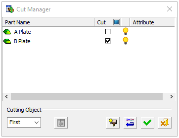
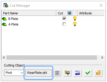
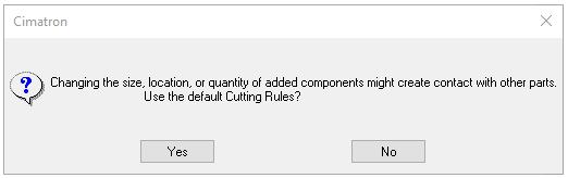
Manual interaction with cut status will not re-order the Cut Manager list. Only by having the system re-run the cutting analysis will the list order change.

Cimatron 2025 lists the parts based on the random order of analysis.

Cimatron 2026 lists the parts according to their initial cut status.

Display the cutting object names Picture 45

Many parts and small sub-assemblies contain one or more cutting object parts. These valuable solid objects create the correct pocket when placing a component, and advanced Cimatron users will often even assign the cutting object a descriptive name, such as Wear plate pocket or Lifter rod hole. Until now there was no field in the assembly Add function to display the cutting object names. The only thing shown was whether the cutting object was the first or second in the part being added.

  • Cimatron 2026 is able to show not only the cutting object order but also the cutting object name.

  • Many parts only have a default cutting object name, but for those who have added distinct names, these are now visible and provide even more clarity to the Cut Manager process.

In Cimatron 2025 we only know that the cutting object being analyzed is the first one in the part being added.

In Cimatron 2026 we now see the descriptive name that has been assigned to each cutting object part.

Saved Cut Manager settings Picture 45

When parts added to an assembly require custom settings of the Cut Manager, it’s important that these be retained and displayed for any further editing later on. This capability has been enhanced to include the addition of sub-assemblies. Now each setting for how each part in the sub-assembly cuts the various other assembly parts is fully recorded and saved. Custom settings will be correctly shown during an edit operation.


In Cimatron 2026 all custom settings for each component of an added sub-assembly are stored and displayed so that every edit operation can reflect the true status of cuts.

Cut Manager alert messages Picture 45

In Cimatron 2026 we have taken the opportunity to re-word and clarify an alert message that appears when approving changes to added components in an assembly. Now the question being asked is more understandable – should the default cutting rules for the added part be used or not? This alert is issued when Cut Manager settings are not at the component default, and one or more of these changes are taking place:

  • The edit changes the size of the component.

  • The edit changes the location of the component in such a way that the cutting analysis is very different.

  • The edit changes the quantity of the component in such a way that the cutting analysis is very different.

The alert message will be issued not only for edits of single components, but also for edits of added small sub-assemblies. This is possible because the cut manager status of added sub-assemblies is now retained.

The alert message will no longer be issued as a confirmation step of your own Cut Manager changes. Accessing the Cut manager prior to approving an edit is signal to the system that these are your desired settings. There is no reason to ask for approval in such a case. This change will eliminate the frequent appearance of this alert when it was not wanted.

The cut manager alert message now asks in specific terms whether the default cutting rules should be applied or not.

Integration with Excel

Empower Mold & Die Setup with Excel Integration Picture 43

The Mold and Die Setup tool is designed to be used to automate the design processes. Over the years, we received many requests to add more functionality to Setup.

It is now possible to empower and simplify Setup by Integrating with Excel to perform complicated calculations, optimizations, and to interact with the user using Excel dialogs.

This Integration feature consists of:

  • Export the entire Setup to an Excel file.

  • Read data from an Excel file, and update requested parameters in the Setup

Picture 1


Picture 1

Click the Export to Excel button and click Open the excel. The default Excel file is automatically copied to the current folder, and is used to store the exported data.

After export is complete and the file is opened,
‎all the parameters in every Setup tab are stored sequentially in the 10_Get-from-Cimatron sheet.

Picture 1

Picture 1

Use all the capabilities of Excel to manipulate the exported
data, apply calculations, lookup tables, and even macros.
The processed data is stored in in the
20_Send-to-Cimatron sheet

In the Setup dialog, click the Read from Excel button, and select the source Excel file (cim-Excel.xlsx).

The relevant parameters in the Setup are updated using the data read from the Excel file.