Deviation Map 


Access: Open this function from the following location:
-
Select Analysis > Main Tools > Deviation Map from the menu bar.
Calculates the deviation (distances) between two versions of a part, it can also be used to highlight the interference between parts. This function then shows the distances as a color-coded map.
Deviation Map is normally used to find out how much material has been added or removed between two versions of a part, you can overlay the new part on the old one by either adding it to the assembly or importing it before running the function.
It can also be used to highlight the interference between a part and other selected parts. When used on two or more different components, the function highlights any material shared between the first and the subsequent selections, providing an accurate interference check.
The results of either analysis are presented using a color-coded display, which can be clicked to display the distance between features.
General Interaction
The following is the Feature Guide for Deviation Map.
|
|
|
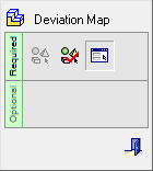
Required Step 1 ![]() : Pick the original object or face(s) and then <exit><exit>.
: Pick the original object or face(s) and then <exit><exit>.
Required Step 2 ![]() : Pick the target object or face(s) and then <exit><exit>.
: Pick the target object or face(s) and then <exit><exit>.
Required Step 3 ![]() : Set the parameters on which the analysis is to be based.
: Set the parameters on which the analysis is to be based.
Detailed Interaction
See Options and Results.