Die Plate Compensation  : Options and Results


Access: Open this function from one of the following locations:
-
Select Die Design > Geometry Manipulation > Die Plate Compensation from the menu bar.
-
Select Geometry Manipulation > Die Plate Compensation from the following Die Design Guide: Die Process Design Guide (Forming).
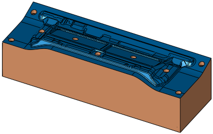
Compensate the bend on the upper and lower die plates to prevent the work piece from being stuck in the die tools when the press is open.
Required Step 1 
-
Pick the object(s) to bend. At this stage you can either define a new part or create the feature in the active part. If there is only one assembly (no sub-assemblies), the assembly is automatically selected.
The following options are displayed:Part file or assembly file and active part = assembly:
Assembly file and active part = part: 

The Create in Active Part toggle option is only available in an assembly file and if the active part is not an assembly.
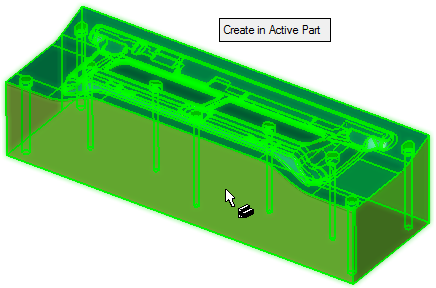
Create in Active Part
This is a toggle option Create in Active Part / Create in New Part that enables you to either create the feature in the active part or to define a new part.
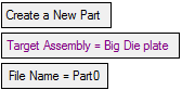
If the Create in New Part option is selected, the following additional parameters are displayed:
Create in New Part
Create the feature in a new part.
Target Assembly
Select the target assembly.
File Name
Enter the file name of the new part. The default name is Part0; if this part already exists in the assembly, the part is named Part1, Part2, etc.
Required Step 2 
-
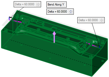
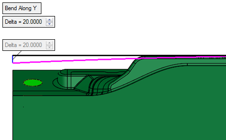
Define the bending direction and magnitude (delta at the ends). You can bend along the X or Y axis; a directional arrow is displayed to flip the bending direction.
Bend Along X
This is a toggle option Bend Along X / Bend Along Y enabling you to select the bend axis.
Delta
Set the bend delta at the ends.
In addition to the parameters, the following additional data is displayed:
-
A gray transparent plane is displayed that reflects the XY bounding box with respect to the flip arrow direction.
-
A black line that represents the original constraint.
It is displayed in the middle of the XY gray active plane from -X to +X for the Bend Along X option, or from -Y to +Y for the Bend Along Y option. -
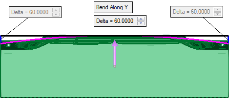
2 blue lines that reflect the Delta value, displayed at the ends of the black line.
A dimmed label with the defined delta distance is attached to these blue lines. -
A purple arc whose radius reflects the delta with respect to the length of the black line.
Note: The Delta value should be smaller than the length of the black line, otherwise the arc cannot be created.

-
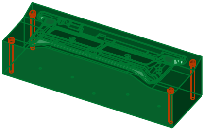
Optional Step 1 
- Click the faces to keep in the same position. These would be the faces that belong to the body selected in step 1.
- Click OKOK
 or ApplyApply
 in the Feature Guide to complete the function.
During parameter definition:
After execution:
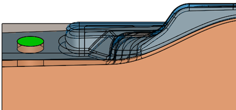
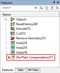
When completed, the new Die Plate Compensation feature will appear in the Feature Tree