Direction Analysis  : Options and Results

Access: Open this function from one of the following locations:
-
Select Analysis > Main Tools > Direction Analysis from the menu bar.
-
Select Parting > Draft Angle Tools > Direction Analysis from the menu bar.
-
Select Parting Analysis Tools > Direction Analysis from the Mold Design Guide Toolbar or Parting Guide Toolbar.
-
Select the Optional Step 1 in the New Direction function.
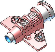
Analyze selected faces and visualize their draft angle with reference to a defined direction.
Required Step 1 
-
PickPick faces or objects of a part for draft angle analysis (or in the Assembly environment, from the activated part). If there are internal areas that you want to exclude, only select the faces that you want to include in the analysis.
Component
All faces selected
-
Press exitexit when you have finished the selection.
Note: Faces from parts that have not been activated will be ignored during the picking operation.
Required Step 2 
-
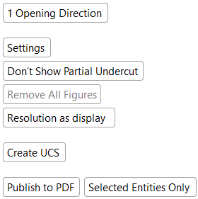
Step 2 is automatically activated after exitingexiting Required Step 1 and displays a set of screen parameters that allow you to set the analysis parameters. See the Parameters section below for a detailed description of all the available screen parameters for this function.
-
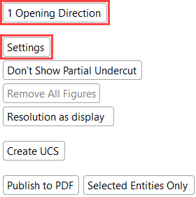
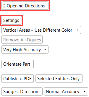
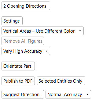
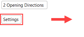
Select Settings to display either the Draft Angle Analysis or Settings color dialog, depending on the analysis method selected. For example, if the 1 Opening Direction toggle option is selected, the Draft Angle Analysis dialog appears when Settings is selected. If the 2 Opening Directions toggle option is selected, the Settings dialog appears (see the images below).
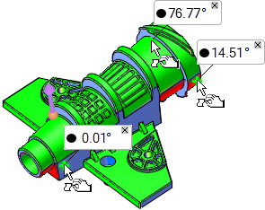
Note that the draft angle is displayed when moving the cursor over the faces selected for assignment. Also, note that the direction arrow is displayed with the default direction Z of the active UCS of the activated part.
1 Opening DirectionThe draft angles are color coded and can be modified by selecting Settings to display the Draft Angle Analysis dialog. |
||
|
|
|
|
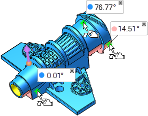
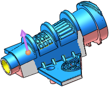
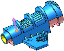
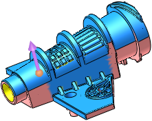
2 Opening DirectionsThe draft angles are color coded and can be modified by selecting Settings to display the Settings dialog. |
||
|
|
|
|
|
Note that the each draft angle when displayed includes a colored circle |
||
-
Select Close
 in the Feature Guide to complete the function.
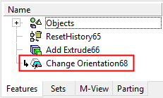
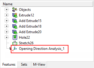
When completed, if the orientation of the selected geometry was changed, the Change Orientation feature will appear in the Feature Tree.
Parameters
|
1 Opening Direction / |
This toggle option determines the analysis method.
|
||||||||||||
|
Settings |
Display the Draft Angle Analysis or the Settings dialog, depending on the analysis method selected – 1 Opening Direction or 2 Opening Directions. The draft angle of the model is automatically color coded according to the default color map values based on zone thresholds.
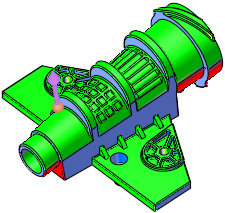
1 Opening Direction – Draft Angle AnalysisCimatron runs the Draft Angle Analysis on the selected faces according to the selected direction. You can change the arrow direction and the analysis will be updated automatically. Display the Draft Angle Analysis dialogDraft Angle Analysis dialog. See below for additional information.
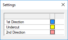
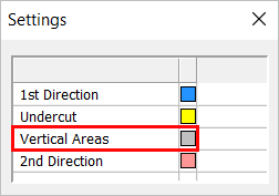
2 Opening Directions – SettingsThe Settings dialog is displayed.
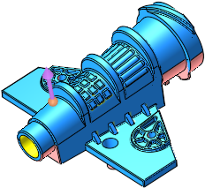
The Settings dialog displays the color coding of the part:
You can add the vertical areas to either the 1st or 2nd opening directions. Notes:
|
||||||||||||
|
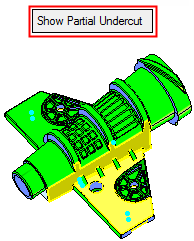
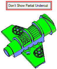
Show Partial Undercut / |
This is a toggle option Show Partial Undercut / Don't Show Partial Undercut to enable you to show partial undercuts for analysis, or not to show them. For all system calculations, there is a correlation between the required accuracy level and the duration of the calculations; setting a higher accuracy level will extend the calculation time.
This option is displayed if the 1 Opening Direction option is selected. |
||||||||||||
|
Vertical Areas - Show Different Color / |
Toggle option that allows you to add vertical areas to the 1st Direction, 2nd Direction, or assign them to a separate color. This toggle parameter is only available for selection when the 2 Opening Directions option is selected.
|
||||||||||||
|
Remove All Figures |
Click the Remove All Figures button to remove all the angle value labels from the display. This option is grayed out if there are no angle value labels in the display. |
||||||||||||
|
Normal Accuracy |
This is a dropdown list of options to define the accuracy level of the faceting tolerances. The following options with their corresponding tolerances are available:
This option is displayed if the 2 Opening Directions option is selected. |
||||||||||||
|
Resolution as Display / |
Use this toggle option to determine the resolution on which the analysis will be based. For all system calculations, there is a correlation between the required accuracy level and the duration of the calculations; setting a higher accuracy level will extend the calculation time.
This option is displayed if the 1 Opening Direction option is selected. |
||||||||||||
|
Create UCS |
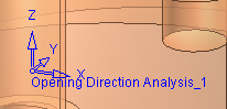
Create a new UCS at the center of the bounding box of the selected object/faces. This creates a UCS named Opening Direction Analysis #<index number>. The Z direction of the created UCS is the same as the current arrow direction. A feature for the new UCS is created in the Feature Tree.
This option is displayed if the 1 Opening Direction option is selected; however, the UCS may be used to set an direction for the 2nd opening direction. |
||||||||||||
|
Orientate Part |
Orientate the part to review the opening direction (on Z) and also undercuts. This may be used for parts that are hard to position in the mold. In this mode, you can rotate the part by dragging it freely, providing an instant analysis of the core, cavity, and undercuts to help you to find the right orientation. When this parameter is selected, the Orientate Part mode displays a separate set of parameters dedicated to orientation. This option is displayed if the 2 Opening Directions option is selected. |
||||||||||||
|
Publish to PDF |
Publish to PDF to create 3D PDF files that include parts and assemblies from Cimatron. When the Publish to PDF button is selected, a dialog is displayed giving you additional controls before the selected entities are exported to PDF. |
||||||||||||
|
Selected Entities Only / |
Publish selected entities only or publish the entire part. |
||||||||||||
|
Suggest Direction |
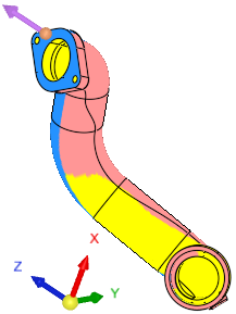
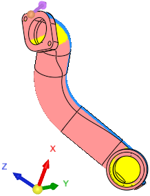
Let the system find the optimum orientation direction. When this option is selected, the system analyzes the best orientation for the mold's opening direction (a crucial initial step of mold design) with the least amount of undercuts. This is especially useful for parts with an ambiguous or hard to find parting line (for example, automotive pipes). This option also appears in the Orientate Part mode described above. If Suggest Direction is invoked in step 2 of the function, the direction arrow will indicate the optimal opening direction (the part orientation remains, the direction arrow changes). In addition, the By Angle direction function is displayed, enabling the direction angle to be fine tuned. The By Angle function does not appear in the Orientate Part mode. If Suggest Direction is invoked within the Orientate Part mode, this will rotate the part so that the optimal opening direction in on the Z direction (the part orientation changes, the direction arrow remains). These examples show the differing results depending on where the Suggest Direction operation is invoked to find the orientation direction with the least amount of undercuts
A progress bar is displayed indicating the progression of the operation. Press ESC to interrupt/stop the operation. Note: To change the actual orientation of the part, click Orientate Part and use the Suggest Direction option there. This option is displayed if the 2 Opening Directions option is selected. Set the required accuracy level in the adjacent option. |
||||||||||||
|
Normal Accuracy |
Set the accuracy level for the orientation calculation. For all system calculations, there is a correlation between the required accuracy level and the duration of the calculations; setting a higher accuracy level will extend the calculation time. This option is displayed if the 2 Opening Directions option is selected. |
||||||||||||
Additional information on the Draft Angle Analysis dialogAdditional information on the Draft Angle Analysis dialog
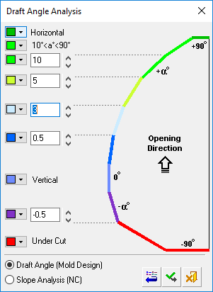
Draft Angle Analysis Dialog
-
Select Settings in the screen parameters. The Draft Angle Analysis dialog is displayed.
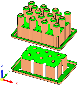
Displaying draft angle analysis
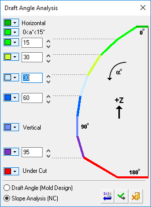
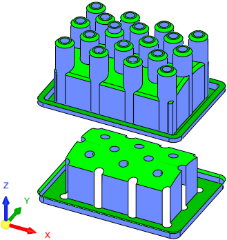
The draft angle of the model is automatically color coded according to the default color map values based on zone thresholds. As shown above, the opening directional arrow is in the +Z direction, clearly showing the faces that are considered vertical and horizontal.
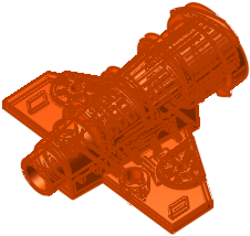
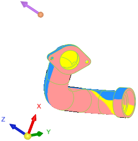
An example of an analysis showing an under cut area can be seen hereseen here. In this case, the opening directional arrow is in the -X direction.
The color map values (based on zone thresholds) can be modified (see Changing the Colors section below) and are divided into the following zones:
-
Horizontal
-
10° < a° < 90° for Draft Angle Analysis
(in the Cimatron MoldDesign application)
0° < a° < 15° for Slope Analysis
(in the Cimatron Numerical Control (NC) application) -
2 user-definable thresholds
-
Vertical
-
1 user-definable threshold
-
Undercut
Cimatron runs the Draft Angle Analysis on the selected faces according to the selected direction. You can change the arrow direction and the analysis will be updated automatically.
The draft angles of points can also be displayed (see Displaying the draft angles of points below).
Notes:
-
Default colors and their values can be defined in Tools > Preferences > Modeling > General.
-
The displayed color changes are only temporary. Once the function is exited, the original colors of the objects are displayed.
-
The default color of objects that are not split is defined in Tools > Preferences > Modeling > Color > Geometry (objects).
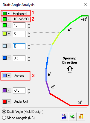
Changing the colors
Select the color to be changed and select the required color from the Color Palette dialog.
The new color is immediately displayed in the color button of the relevant angle segment. When you click ApplyApply
 in the Draft Angle Analysis dialog, the color of all appropriate faces in the model that match the zone thresholds are changed.
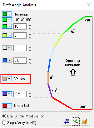
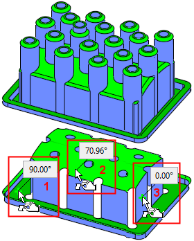
Displaying the draft angles of points
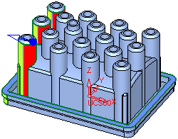
To display the local draft angle at any point on a face, move the cursor over the appropriate face. The cursor changes to
and the local angle at the point indicated by the cursor is displayed in a label (if required, pick the face to attach the label to it).The presented angle is between the direction arrow and the tangential line on the cursor point. As shown below, the opening directional arrow is in the +Z direction. Also, note that the Remove All Figures option is available (not grayed out) as angle value labels are attached to faces (select this option to remove these labels from the display).
-
-
Modify the threshold values on the dialog by entering new values manually or by clicking the arrows to increase or decrease the values by increments of 0.5.
-
Either click Restore DefaultsRestore Defaults
 to restore the default colors and values from Preferences, ApplyApply to apply the new draft angle color ranges, or CancelCancel
  to exit the function.
Notes:
-
Each operation that changes any of the objects (split, attach faces, delete, etc.) is followed with an immediate recalculation of the draft angle analysis.
-
If a Parting Surface exists, it is also included in the draft angle analysis.
-