|
|
Direction Analysis  : Orientate Part

Access: Open this function from one of the following locations:
-
Select Analysis > Main Tools > Direction Analysis from the menu bar.
-
Select Parting > Draft Angle Tools > Direction Analysis from the menu bar.
-
Select Parting Analysis Tools > Direction Analysis from the Mold Design Guide Toolbar or Parting Guide Toolbar.
-
Select the Optional Step 1 in the New Direction function.
Analyze selected faces and visualize their draft angle with reference to a defined direction.
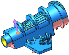
Orientate the part to review the opening direction (on Z) and also undercuts.
This may be used for parts that are hard to position in the mold. In this mode, you can rotate the part by dragging it freely, providing an instant analysis of the core, cavity, and undercuts to help you to find the right orientation.
The Orientate Part mode displays a separate set of parameters dedicated to orientation.
The following parameters are displayed.
|
|
|
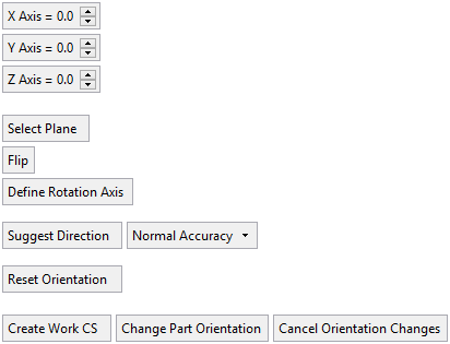
Parameters
|
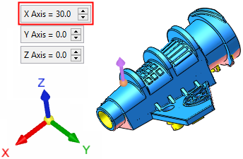
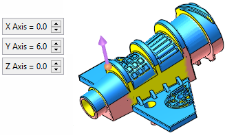
Axis |
Rotate the part around each of the three main axes. Enter rotation angles; the part is rotated accordingly.
These angle values are displayed as zero when the Direction Analysis function is invokedinvoked or when using the Orientate Part option. |
||||||
|
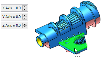
Select Plane |
Select a plane. The part orientates so that the direction is normal to the selected plane. The Axis values are updated accordingly.
|
||||||
|
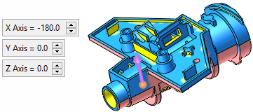
Flip |
Flip the part around the selected plane. If a plane has not been selected, the part is flipped around its X axis.
|
||||||
|
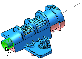
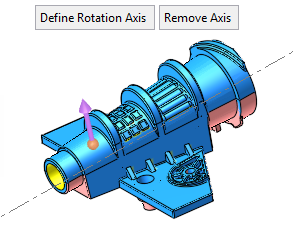
Define Rotation Axis |
Define an axis on which the part will be rotated. The axis may be selected by picking 2 points, a linear edge or curve, or a circular face, edge, or curve.
All screen parameters are hidden while in the rotation axis definition mode. While in this mode, if the Esc or MMBMMB are clicked, you exit this mode without any changes (however, if an axis was already defined, it stays defined). When a valid axis is defined, the system exits the axis definition mode and the model will only rotate around the defined axis. Once an axis is defined, the Remove Axis screen parameter is displayed. Select this parameter to remove any axis that was defined. |
||||||
|
Suggest Direction |
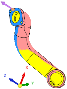
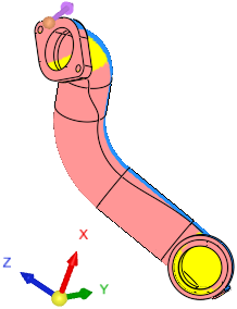
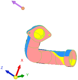
Let the system find the optimum orientation direction. When this option is selected, the system analyzes the best orientation for the mold's opening direction (a crucial initial step of mold design) with the least amount of undercuts. This is especially useful for parts with an ambiguous or hard to find parting line (for example, automotive pipes). This option also appears in the Step 2 of the function. If Suggest Direction is invoked within the Orientate Part mode, this will rotate the part so that the optimal opening direction in on the Z direction (the part orientation changes, the direction arrow remains). These examples show the differing results depending on where the Suggest Direction operation is invoked to find the orientation direction with the least amount of undercuts
A progress bar is displayed indicating the progression of the operation. Press ESC to interrupt/stop the operation. Note: To change the actual orientation of the part, click Orientate Part and use the Suggest Direction option there. |
||||||
|
Normal Accuracy |
Set the accuracy level for the orientation calculation. For all system calculations, there is a correlation between the required accuracy level and the duration of the calculations; setting a higher accuracy level will extend the calculation time. |
||||||
|
Reset Orientation |
Reset the part to its orientation prior to entering the orientation mode (before the Orientate Part button was pressed). |
||||||
|
Create Work CS / |
This is not a toggle option. This screen parameter displays either Create Work CS or Update Work CS. Create Work CS is displayed if a Work CS does not exist in the part. In this case, a work CS feature is created in the direction of the reposition. This Work CS is used to determine the opening directions. Update Work CS is displayed if a Work CS already exists or if several parts are selected, some with and some without a Work CS. If a Work CS already exists, its orientation is changed accordingly. For both Create and Update Work CS, when the mode is exited, the part orientates back to its original position. Mixed Input In case of a mixed input (multiple selected parts, some with and some without a Work CS), a Work CS is added where it is missing or updated if it already exists. Upon creating or updating a Work CS, the orientation mode is exited. |
||||||
|
Change Part Orientation |
Move all the entities in their parts to fit the new position and exit the orientation mode. |
||||||
|
Cancel Orientation Changes |
Reset the orientation and exit the orientation mode. |
|