Array of Frames 

Access: Open this function from the following location:
-
Select Views > View Creation > Array of Frames from the menu bar.
Create an array of drawings on a single sheet with each drawing in its own frame.
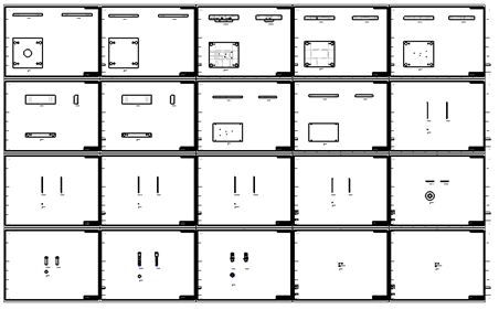
This function automates the creation of dozens of drawings at once, usually for each one of the parts in a Die sub-assembly. Arrays of drawings are very common in the Die industry, where a drawing of all the parts is created, printed, and hung on the wall where the Die is manufactured.
|
|
This image shows 20 drawings created automatically for 20 different parts. |
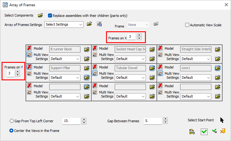
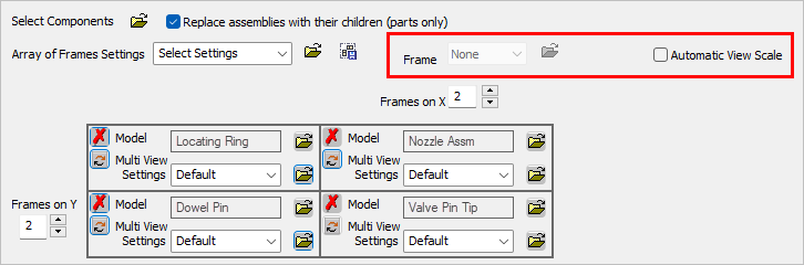
The Array of Frames dialog is displayed below. This dialog is used to define and edit an array of frames and include content (assembly/part) into each frame.
|
|
In this topic: |
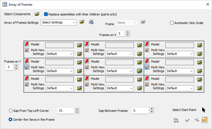
Load assemblies and/or parts so that each selected entity is assigned a frame in the array. Multiple entities may be selected globally (using the Select Components option) with each entity automatically assigned its own frame or individual entities can be loaded locally into each frame (using the Model selection option in each frame). The content of each frame is converted into a drawing.
See also:
Dialog structure
The following parameters appear in the dialog.
|
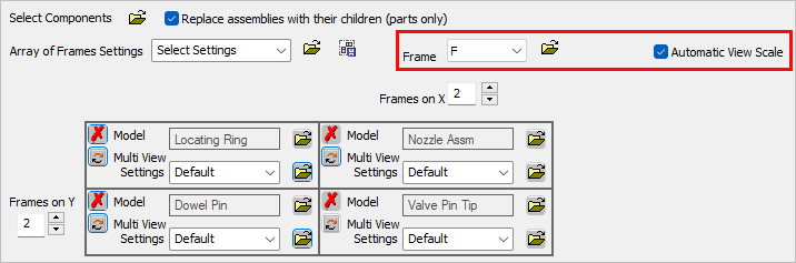
Select Components |
Select the components to be added to the cells of the frame. A browse button displays the Cimatron Explorer. Multiple assemblies and/or parts may be selected. Each selected item is assigned its own frame in alphabetical order (case sensitive).
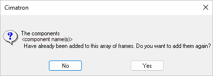
If there are not enough frame cells in the dialog, additional columns are automatically added in the dialog to accommodate the selected components. When selecting one or more components that already exist in the array of frames, a message is displayed requiring confirmation to add the components again.
|
||||||||
|
Replace assemblies with their children (parts only) |
This checkbox defines whether selected assemblies or only their parts are inserted into frames. This only applies to assemblies selected from the Select Components option above (not from the cells). When this checkbox is ON (the default) and assemblies are selected, only the children of these assemblies (parts only, up to the deepest level) are inserted into the frames, where each part is assigned its own frame. Non-printed parts (those not visible in the view) are not included. However, a Single Unit SA is shown but not its parts. When this checkbox is OFF and assemblies are selected, the assemblies themselves are inserted into the frames, where each assembly is assigned its own frame. |
||||||||
|
Array of Frames Settings |
Load the required array of frames settings file or save the current settings. The settings save all the values in the dialog except the models and start point (amount on X, Y, Spacing, and Multi View Settings used for each frame). The dropdown list shows all the settings saved in the last used location. The array of frames settings files have the AFS extension. Use the adjacent Save Settings button Loading a settings file will apply its settings to all views. The default Array of Frames settings are stored in the Default_mm.afs and Default_inch.afs files in the following folder:
...\ProgramData\Cimatron\Cimatron\2026.0\Data\templates\Array_Of_Frames |
||||||||
|
Frame |
Set the Frame controls. These are the same controls as the Frame Settings function. Default = None. The Frame option is only available if the Automatic View Scale checkbox is ON. When the Frame option is available, the The selected frame and the status of this option are kept in the Array of Frames template. The Frame settings are stored in FRM files in the following folder:
...\ProgramData\Cimatron\Cimatron\2026.0\Data\frames\ If a view cannot fit into a frame, the Model name in the relevant frame is highlighted and a warning message is displayed listing the relevant models. For additional information, see View - Frame Size below. Empty cells do not have a frame created around them. In the Frame Settings function, when dragging a frame, a toggle option is displayed enabling you to choose whether or not to also drag the frame contents. |
||||||||
|
Automatic View Scale |
When this checkbox is OFF (the default), the system uses the view scale as defined in the Multi View Settings. When the Automatic View Scale checkbox is OFF, the frame size selected by the system is from the list of standard frame sizes that can fit the view defined by its Multi View Settings. The size of all cells is the same as that required for the largest cell in the array.
When the Automatic View Scale checkbox is ON, the Frame controls become available. Any frame may be selected, as the view in each frame is automatically scaled. For a usage example, see Automatic View Scale below. |
||||||||
|
Frames on X / Y |
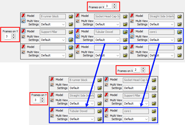
Set the number of frames in the X and Y directions of the array.
When reducing rows or columns, if empty cells are available, the removed cell values are moved and integrated into the new array structure while keeping the left to right, top to bottom cell order.
|
||||||||
|
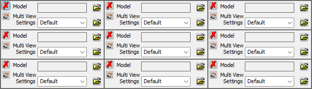
Array of Frames entity selection area |
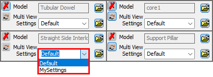
Load assemblies and/or parts so that each selected entity is assigned a frame in the array. Multiple entities may be selected globally (using the Select Components option) with each entity automatically assigned its own frame or individual entities can be loaded locally into each frame (using the Model selection option in each frame). The content of each frame is converted into a drawing. When locally loading individual entities into each frame using the Model selection option, a browse button displays the Cimatron Explorer. For each frame, a single assembly or part may be selected. Regardless how an assembly or part is loaded into each frame, the Multi View Settings option enables you to define the kinds of views to be produced.
|
||||||||
|
Gap From Top Left Corner |
Set the distance between the top left of the view and the top left outer corner of the frame in both the X and Y directions. Default = 15 mm or 3 inches. |
||||||||
|
Gap Between Frames |
Set the distance between frames in both the X and Y directions. Default = 5 mm or 1 inch. |
||||||||
|
Select Start Point |
Position the array of frames in the graphics window by picking a point that will be the top left corner of the array. If a start point is not selected, the system positions the array in a default location. |
||||||||
|
Center the Views in the Frame |
Position the drawings in the center of each frame. By default, this option is ON (selected). Cimatron retains the last-used setting for this option when a new Array of Frames dialog is opened. |
Dialog buttons
The following buttons appear in the dialog.
|
|
Manual Preview: Previewed results are not automatically displayed on the screen. The results of the operation are displayed after applying the changes. |
|
|
OK: Accept the changes, perform the operation, and close the current dialog/task. The array of drawings is produced on a single sheet. |
|
|
Apply: Accept the changes, perform the operation, and keep the current dialog/task open. |
|
|
Cancel: Cancel all changes and close the dialog/task without saving the settings. |
Usage examples
Automatic View Scale
The examples below were created with identical settings with the Automatic View Scale OFF and ON. The same size frames are used.
Automatic View Scale OFF
Four frames are created in a single sheet. Each frame has the model loaded with its own Multi View settings.
When the Automatic View Scale checkbox is OFF, the frame size selected by the system is from the list of standard frame sizes that can fit the view defined by its Multi View Settings. The size of all cells is the same as that required for the largest cell in the array.
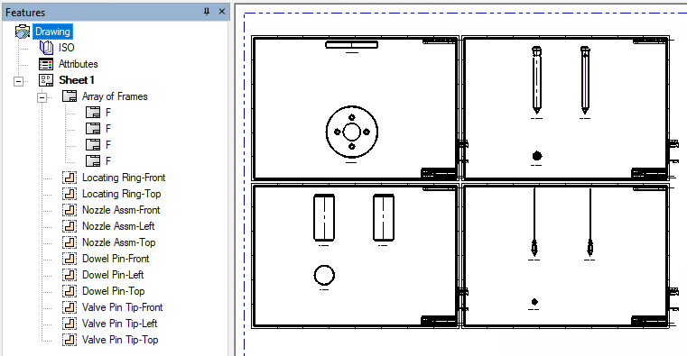
In this case, the system selects frame size F, as shown in the Drawing Tree.
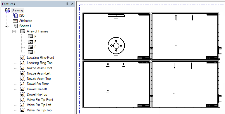
Automatic View Scale ON
Four frames are created in a single sheet. Each frame has the model loaded with its own Multi View settings.
When the Automatic View Scale checkbox is ON, the Frame controls become available. Any frame may be selected, as the view in each frame is automatically scaled.
In this case, the same size frame size (F) is selected (as shown in the Drawing Tree) to clearly show the parts automatically scaled.
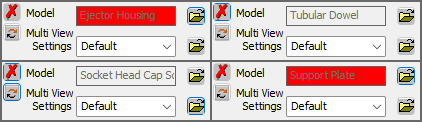
View – Frame Size
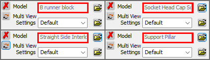
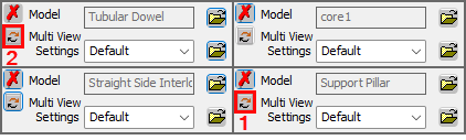
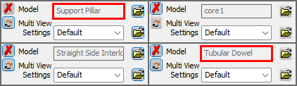
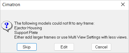
If a view cannot fit into a frame, the Model name in the relevant frame is highlighted in RED and a warning message is displayed listing the relevant models.
|
|
|
|
|
Skip |
Skip the problematic models; this creates empty frames for those models. This is the default option (clicking Enter or the Space Bar will select it). |
|
Edit |
Return to the Array of Frames dialog to edit it, as suggested in the message. |
|
Cancel |
Cancel the entire operation. |