|
|
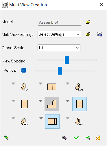
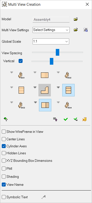
Multi View Creation 

Access: Open this function from one of the following locations:
-
Click
in the toolbar. -
Select Views > View Creation > Multi View Creation from the menu bar.
-
Select Multi View Creation on the popup menu (right-click the graphics area).
-
Select Multi View Creation on the popup menu in the Drawing Tree (right-click the currently active Sheet
 in the Drawing Tree).
Create multiple views in a single operation.
This feature defines the type of view(s) that will be produced from the selected entity.
From the Multi View Creation dialog, you can select up to nine (9) views, which are automatically displayed.
|
|
|
Settings and options
|
Model |
Select the model for which to create views. |
||||
|
Multi View Settings |
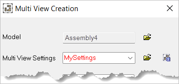
Load the required Multi View Settings file (see View Settings below). Loading a settings file will apply its settings to all views. This file stores the following Multi View Settings:
After loading a settings file, if you make additional changes to the dialog settings, the settings filename in the Multi View Settings box will display in RED, indicating that the file was originally the source for the settings but has since been altered by you.
The default Multi View Settings are stored in the Default.mvs file in the following folder:
...\ProgramData\Cimatron\Cimatron\2026.0\Data\templates\Multi_View\ |
||||
|
Global Scale |
Set the scale of the views from the dropdown list. This option is similar to the one for View Creation, with the addition of the Auto Scale option that automatically scales the multi views so that they fit into the drawing frame (if one exists). If no frame exists and the Auto Scale option is selected, the views are created using the 1:1 scale.
|
||||
|
View Spacing |
Use the View Spacing slider control to adjust horizontal and vertical spacing between the views.
Moving the slider to the right increases spacing between the views. Moving the slider to the left reduces spacing. |
||||
|
Vertical |
Select the Vertical checkbox to enable the Vertical slider control. When this checkbox is marked
Moving the slider to the right increases vertical spacing between the views. Moving the slider to the left reduces spacing. When this checkbox is OFF |
||||
|
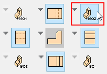
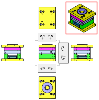
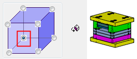
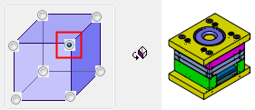
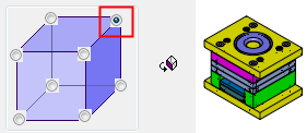
<views> |
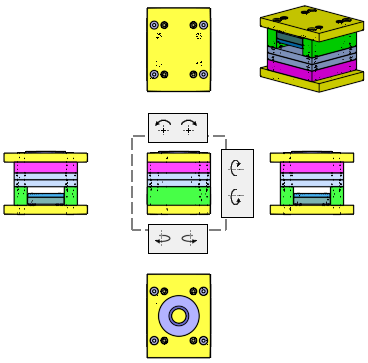
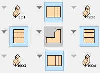
Define up to nine (9) views in a single operation, with the corner views defined as ISO views.
When a view is selected, it is immediately displayed.
The middle view has rotation buttons on its top, right, and bottom sides (2 buttons on each side) that rotate the view by 90°. The arrows on the top rotate the view around the Z axis, the arrows on the right rotate it around the X axis, and the arrows on the bottom rotate it around the Y axis. Any rotation results is a respective change in the other views and their icons in the dialog. The ISO views are not affected by these rotations. |

Dialog buttons
|
|
Open: Browse to and select/open the required file. |
|
|
Save Settings: Save user-defined defaults. This saves the defined multi view settings in a .MVS file. The default Multi View Settings are stored in the Default.mvs file in the following folder:
...\ProgramData\Cimatron\Cimatron\2026.0\Data\templates\Multi_View\ |
|
|
Part Filter: Display the Part Filter, which enables you to hide or show items in the view. |
|
|
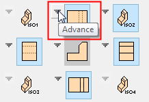
Expand/Collapse: Expand the dialog to show the Advanced options. Collapse the dialog to hide them. Expand
|
|
|
OK: Accept the changes, perform the operation, and close the current dialog/task. |
|
|
Apply: Accept the changes, perform the operation, and keep the current dialog/task open. |
|
|
Cancel: Cancel all changes and close the dialog/task without saving the settings. |

View Settings
The default Multi View Settings are stored in the Default.mvs file in the following folder:
...\ProgramData\Cimatron\Cimatron\2026.0\Data\templates\Multi_View\
Expand ![]() / Collapse
/ Collapse ![]() displays the default settings for all multi views, which control how each view is displayed. In addition to these global settings, the display of each view can be controlled using local settings (via the Advanced settings option- see below).
displays the default settings for all multi views, which control how each view is displayed. In addition to these global settings, the display of each view can be controlled using local settings (via the Advanced settings option- see below).
|
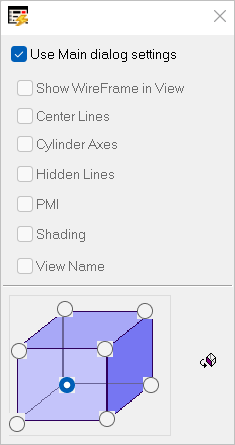
Default (main dialog) display settings |
Specific view display settings |
||
|
|
Adjacent to each view type in the dialog is an Advanced settings option, which enables you to control the settings for that specific view. These options are the same as those in the main dialog. When the Use Main dialog settings checkbox is ON, all other checkboxes receive their status from the main dialog and are grayed out. When the Use Main dialog settings checkbox is OFF, the other checkboxes are available for use to define view settings for that specific view. These settings are also available for simple views.
|

Symbolic Text
Symbolic text can be created automatically with multi views. When this checkbox is ON, Define Symbolic Text ![]() becomes available. Click to display the Text Editor dialog and enter the text of this multi view.
becomes available. Click to display the Text Editor dialog and enter the text of this multi view.
When the checkbox is selected, the text is created at the defined size above the top left corner of the bounding box of all views. If the text includes symbolic text, it is attached to the selected model. When saving multi view settings, the text and all its parameters are saved.
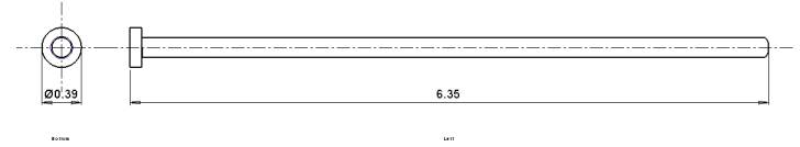
XYZ Bounding Box Dimensions
When this checkbox is marked  , the 3 bounding box dimensions of the part (X,Y,Z) are created. This is especially useful when creating a multi-frame drawing holding multiple parts.
The X and Y dimensions are normally created on the top view (if it is created) and the Z dimension on one perpendicular view. If there is no top view, the system chooses any base view for the first 2 dimensions and any other base view for the 3rd dimension.
In the case of revolved parts, the system creates a single diameter dimension instead of the X and Y dimensions.
Examples
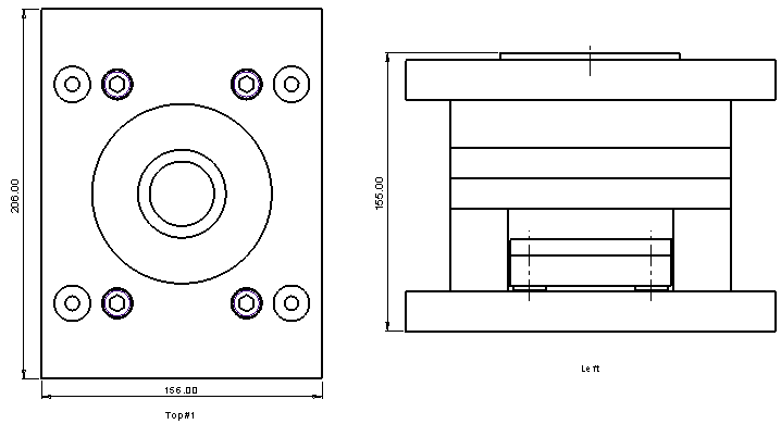
For revolved parts, the system creates a single diameter dimension instead of the X and Y dimensions.
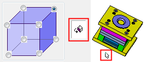
ISO Views
The ISO views have an extra section in their view settings options that allow you can select one of eight (8) possible orientations. In addition, an interactive view button enables you to interactively rotate just that specific view.
|
ISO View Settings dialog |
View settings |
||||||||
|
|
Select one of eight (8) possible orientations or click the interactive button to interactively rotate the view to the required orientation.
|
|