Simple View 

Access: Open this function from one of the following locations:
-
Click
in the toolbar. -
Select Views > View Creation > View Creation from the menu bar.
-
Select View Creation on the popup menu (right-click the graphics area).
-
Select View Creation on the popup menu in the Drawing Tree (right-click the current active sheet
 in the Drawing Tree).
Create a view of a part.
Other available view types
Note: A view is created under the current active sheet (either double-click the sheet name ![]() in the Drawing Tree or right-click it and select Activate Sheet) in the Drawing Tree.
in the Drawing Tree or right-click it and select Activate Sheet) in the Drawing Tree.
Creating a simple view
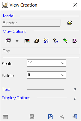
InvokeInvoke View Creation. The View Creation dialog is displayed.
Click ![]() /
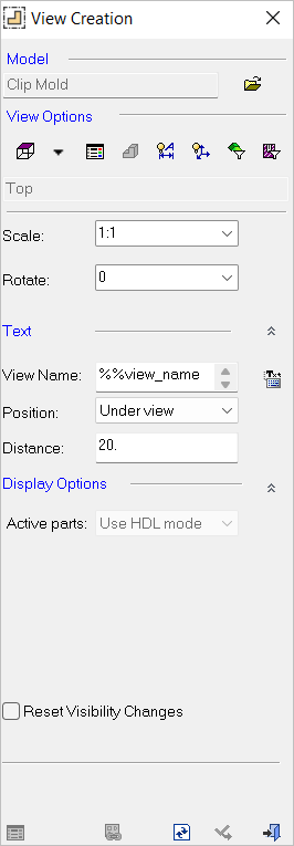
/ ![]() to expand or collapse the dialog as required.
to expand or collapse the dialog as required.
Note: Most of the View, Text, and Display options that appear in the View Creation dialog are also available in Preferences (Tools > Preferences > Drafting > View > Simple View). The parameter default status values are defined in Preferences.
|
Collapsed dialog |
Expanded dialog |
Dialog expanded showing a |
|
|
|
|
Select the Model type you wish to project.
a. From the Model area, click Cimatron Open Model ![]() .
.
b. The Cimatron Explorer dialog is displayed. Select a Cimatron model.
Set the view options.
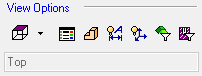
Options
|
|
|||
|
|
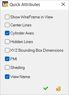
Quick Attributes
|
||
|
|
|||
|
|
|||
|
|
|||
|
|
|||
|
|


Change the projection of the model (it can be changed again later).
Change the Scale and Rotate angle in the View Creation dialog.
In the Text area of the dialog, click Expand ![]() to display the following options:
to display the following options:
Options
|
View Name |
Enter the text either in the Text field or by clicking the Editor button and entering regular text or selecting Symbolic Text. |
|
Position |
Select the Position of the center point of the text from the dropdown menu (if "None" is selected, the other Text parameters in this dialog will be grayed-out). |
|
Distance |
Enter the distance in units from the bounding box of the view (a negative value can also be input). The default values of Position, Text, and Distance are as defined in Preferences. The Text Origin Point can also be defined as with any text entity. |
In the Display Options area of the dialog, click Expand ![]() to display the following options.
to display the following options.
|
|
|
|
Options
|
Active Parts |
Choose how active parts (an assembly, or parts of it, defined as active) are to be displayed in the view. The rendering speed is affected by how the active parts are defined in the view. The available options are:
|
||||||||||||
|
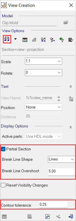
Partial Section |
Show a partial section in the view. This checkbox enables you to control whether to create a section view of only the area of the section line and not of the entire model. (The entire model is not cut, only the area of the section line [between the points].) The Partial Section parameters are displayed in the View Creation dialog when the view is a section view or an M-View section. The default setting for this checkbox and the Contour Tolerance parameter (at the bottom of the dialog) is defined in the Preferences (Tools > Preferences > Drafting > View > Section View). See Preferences for additional information.
When the Partial Section checkbox is ON, the following parameters become available:
These parameters are identical to those appearing in the Break View function. The defaults for these parameters are defined in Preferences (Tools > Preferences > Drafting > View > Partial Section). If one of the break lines is to be drawn outside of the view (touches no geometry) it will not be drawn, as shown below:
|
||||||||||||
|
Reset Visibility Changes |
Resets any changes that were performed on the part back to the default settings of the system. |


Click View Attributes ![]() to set the attributes of the view.
to set the attributes of the view.
Click Regenerate  to view the settings.
Drag the view to the required position and click Apply ![]() to complete the operation.
to complete the operation.
Create a new view or click Close ![]() to exit the operation. (If you exit the function without regenerating, you will receive a message and the regeneration will be performed automatically.)
to exit the operation. (If you exit the function without regenerating, you will receive a message and the regeneration will be performed automatically.)