|
|
Automatic Ordinate  : Editing
![]()
![]()
Access: Open this function from one of the following locations:
-
Click the
button in the toolbar. -
Select Symbols > Automatic Symbols > Automatic Ordinate from the menu bar.
Automatically create ordinate dimensions through circles, arcs, points, splines, and center lines.
Ordinate dimensions can be created in any direction and defined via view entities (two points or a line), allowing alignment with view rotation or angled details. You can also control the ordinate dimension's association with the view on the X-axis as well as its distance from selected points or the view. Additional functionality includes the option of displaying the Base Point dimension (zero point).
Preferences options enable you to set the default for the creation of ordinate dimensions close to the measured point or outside the view and also the default distance of the ordinate dimensions.
Edit an Automatic Ordinate Dimension
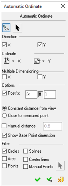
- InvokeInvoke the Automatic Ordinate function. The Automatic Ordinate dialog is displayed.
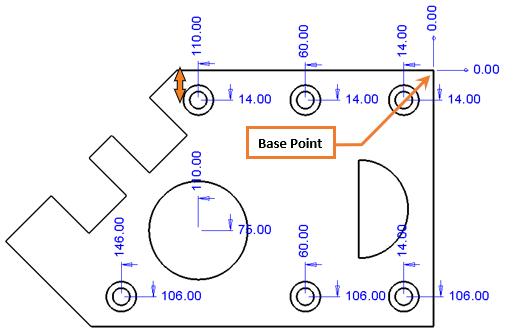
- For this example, pickpick the upper-right corner Base Point as origin.
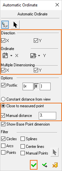
- From the Automatic Ordinate dialog, check the X and Y directions.
- Change the X Ordinate placement to Above View
 and the Y Ordinate placement to Right of View
  .
. - Select Multiple Dimensioning checkboxes for both X and Y.
- Select the option Close to Measured Point.
- Select the option Manual Distance, and set its value to 3.
- PickPick the OK
 button to approve.
Note: Dimensions have been created to the right and above the center points. Also, the distance from center point is the value you selected multiplied with the dimension's font size.
|