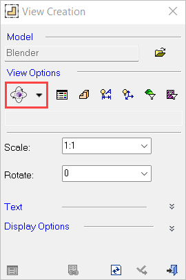
D-View 


Access: A view is created under the currently active sheetactive sheet(either double-click the sheet name ![]() in the Drawing Tree or right-click the sheet name
in the Drawing Tree or right-click the sheet name ![]() and select Activate Sheet). The View Creation dialog can be accessed using one of the following methods:
and select Activate Sheet). The View Creation dialog can be accessed using one of the following methods:
-
Click
in the toolbar. -
Right-click the currently active Sheet item
 in the Drawing Tree and select View Creation.
 -
Right-click the graphics area and select View Creation.
-
Select Views > View Creation > View Creation from the Drafting menu bar.
A D-View is an M-View (a user-defined view in the Part and Assembly environments) that is opened in the Drafting environment. Once positioned in the drafting sheet, it can be manipulated exactly like a regular view.
|
Demo: Press the button below to view a short movie demonstrating the function. |
|
|

Creating a D-View
-
InvokeInvoke the View Creation function.
-
Click the Open File
 button. Select an existing view from the displayed Cimatron Explorer window and click Select to return to the View Creation dialog.
 -
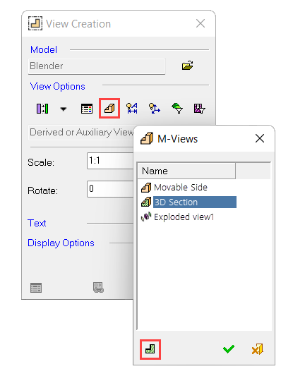
Click the M-View
button in the View Creation dialog. The M-Views dialog appears displaying a list of predefined M-Views and Exploded Views.
-
Select the required M-View or Exploded View to place in the sheet.
-
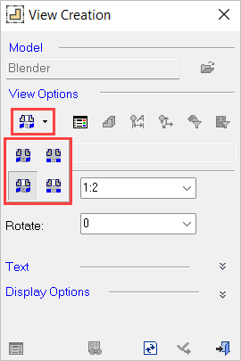
When a Section View is selected (as shown in the example below), the Section Projection
 toggle button is activated enabling you to display the following:
-
Click Section Projection
and click OK  to close the M-Views window. Select the required view from the Section View-Type dropdown list.
-
-
-
The cursor changes as follows
 . Click to display the section view in the required 2D view.
-
-
Alternatively, you can toggle the Section Projection
button to Interactive  and click OK.
-
Click to display the section view in 3D view.
If a D-View is created using a broken section line in the Assembly and Part environments, it is possible to determine along which segment of the section line the sectioned geometry will be displayed in Drafting. The following example shows the result of flipping the section line display direction by clicking on the line itself. The thickened line segment direction is the displayed direction of the geometry.
-
Click OK. The D-View is listed in the Drawing Tree.
From the M-View dialog, you can also select predefined exploded views that were created from an assembly model, as described in steps 1 through 4 above. The result is displayed as follows:
Note: By default, the exploded lines are displayed. You can show or hide specific lines from the View Attributes dialog box, which is displayed by selecting View Attributes ![]() in the View Creation dialog.
in the View Creation dialog.