|
|
Multi Diameter 

Access: Open this function from one of the following locations:
-
Click the
button in the toolbar. -
Select Symbols > GD&T > Multi Diameter from the menu bar.
-
Select Drafting Symbols > Multi Diameter on the popup menu (right-click the graphics area).
Add the multi diameter symbol to the drawing. When you use the Multi Diameter function and click a drafting hole in any direction (normal to view orientation, front, side, etc.) the system analyzes the hole segments and sets major diameters in the Multi Diameter symbol.
|
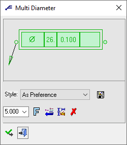
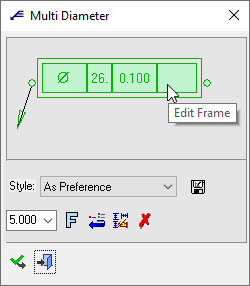
The Multi Diameter dialog displays
|
Below is an example of the symbol:
See Entity Overview for a general description. |
By entering the Multi Diameter Editor, you can then manually add new rows to the Multi Diameter symbol, and define whichever hole type is needed. You can also manipulate the Multi Diameter symbol by changing the order of rows/segments, deleting rows, and adding any prefix, postfix, tolerance or textual values.
Add a Multi Diameter symbol
-
InvokeInvoke the Multi Diameter function.
The Multi Diameter dialog (see below) is displayed.
-
Pick the entity to be dimensioned. This can be a hole or a sketch hole (circles/points/arcs) in all simple views (top, front, side). The system then analyzes the hole segments and sets major diameters in the Multi Diameter symbol.
Examples:
-
Pick a multiple diameter hole
An example of such a hole is shown hereshown here.Top view:
Side view:

This example hole has 3 diameters.
Pick a hole with multiple diameters:
Pick a location on the screen to position the label:
The Multi Diameter symbol is displayed showing the multiple diameters (in this case 2 diameters). Edit the label using the Multi Diameter Editor.
Note: If you subsequently connect the end point of the label to a new hole, the label is updated with the new diameters. For example, if you pick a single diameter hole, only the single diameter is displayed, as shown hereshown here
. -
Pick a point
Pick a sketch point:
Pick a location on the screen to position the label:
The Multi Diameter symbol is displayed showing the default dimension text. Edit the label using the Multi Diameter Editor.
-
-
Edit the label using the Multi Diameter Editor.
-
In the Multi Diameter dialog (see below), change font style
 and character size also, if required.
 -
To complete the current operation and remain in the dialog, press the Apply
 button or <exit><exit>.
To exit the function, press the Close button.
Notes:
-
Right-click the entity itself to access the entity-specific (for editing) and general functions from the popup submenu.
-
Double-click the entity to edit it.
-
See the Symbol notes for additional information.
Edit the displayed labels by using the Multi Diameter Editor
-
Open the Multi Diameter Editor either by clicking the dimension text area in the Multi Diameter label (within the area marked in green when the cursor rolls over the text), or by clicking the green box within the Multi Dimension dialog:
Clicking the dimension text area in the Multi Diameter label:
Clicking the box in the Multi Dimension dialog:
-
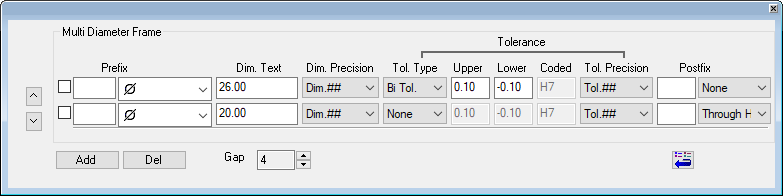
The Multi Diameter Editor is displayed.
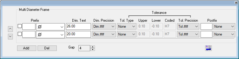
The number of rows that are initially displayed in the dialog corresponds to the number of diameters of the selected hole. If a non-hole entity is picked, a single row is initially displayed showing the default dimension text.
Dialog description:Dialog description:Buttons:

Move a selected row up or down to change its order in the dialog. The new order is reflected in the Multi Diameter label.
Select the checkboxcheckbox at the row you which to move and press the appropriate arrow button.
Examples:Examples:
In this example, the row is moved up.
Add
Add a new row to the dialog. The new row is added at the bottom of the existing rows.
Up to ten rows can be added.Del
Delete the selected row(s). Multiple rows can be deleted, however, you cannot delete all the rows; the dialog must contain at least one row.
Select the checkboxcheckbox at the row(s) you which to delete and press the Del button.Gap
Set the distance between the middle dimensions in the label.
Examples:Examples:
Gap = 0
Gap = 6

Restore the default values to the Multi Diameter Editor. The default values are those that were initially displayed when you invoked the editor.
Parameters:
Select a checkbox to mark a row you wish to move or delete (using the buttons).
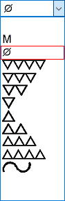
Prefix
Set the dimension prefix by selecting one from the dropdown listdropdown list.
Dim. Text
The dimension text. This field initially displays the contents of the Multi Diameter label, however, the field can be edited and the changes are displayed in the labels.
Dim. Precision
Set the dimension precision by selecting one from the dropdown listdropdown list.
The default option is set in the Drafting Preferences.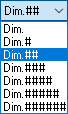
Tol. Type
Set the tolerance type by selecting one from the dropdown listdropdown list.
Upper, Lower, Coded
The Upper, Lower, and Coded tolerances are enabled depending on the selected Tolerance Type, as shown belowshown below.
In these examples, the two "extremes" are highlighted:
If Tol. Type = None, none of the tolerances are enabled.
If Tol. Type = Exact Tol., all of the tolerances are enabled.Tol. Precision
Set the tolerance precision by selecting one from the dropdown listdropdown list.
The default option is set in the Drafting Preferences.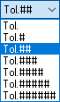
Postfix
Set the postfix by selecting one from the dropdown listdropdown list.

Set the parameters as required. The changes are immediately reflected in the Multi Diameter label.
In the example below, the Multi Diameter Editor is displayed showing a single row with the default dimension text (in this case after picking a sketch point).
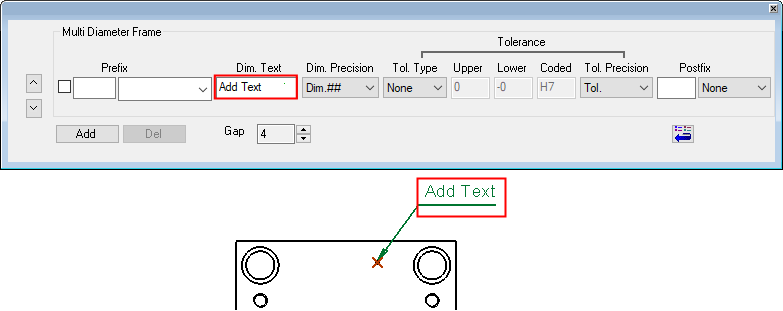
When the Multi Diameter Editor is changed, the changes are immediately reflected in the Multi Diameter label (shown below the editor).
|