Show & Hide Model Symbols 


Access: A view is created under the currently active sheetactive sheet(either double-click the sheet name ![]() in the Drawing Tree or right-click the sheet name
in the Drawing Tree or right-click the sheet name ![]() and select Activate Sheet). The View Creation dialog can be accessed using one of the following methods:
and select Activate Sheet). The View Creation dialog can be accessed using one of the following methods:
-
Click
in the toolbar. -
Right-click the currently active Sheet item
 in the Drawing Tree and select View Creation.
 -
Right-click the graphics area and select View Creation.
-
Select Views > View Creation > View Creation from the Drafting menu bar.
The Show & Hide Model Symbols option allows Product Manufacturing Information (PMI) annotations (which have been assigned earlier to sub-assemblies in the Modeling environment) to be displayed (or hidden) in the Drafting environment. These PMI annotations include Datum marks, Surface Finish marks and Coordinate labeling.
See Product and Manufacturing Information (PMI) for additional information.
Showing/hiding the entities in a view
-
InvokeInvoke the View Creation function.
-
Click the Show/Hide Model Symbols button
in the View Creation dialog.
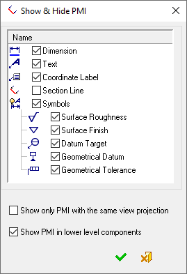
The Show & Hide PMI dialog is displayed.
-
Using the checkboxes, select which entities to see in the view (only the entities that are on the same plane as the view, are displayed), as shown in the examplesas shown in the examples.
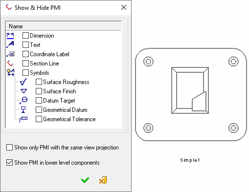
No entities are displayedNo entities are displayed
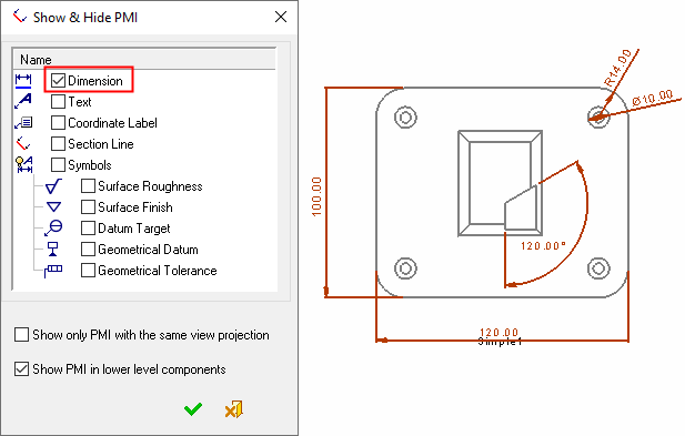
Only the dimension entities are displayedOnly the dimension entities are displayed
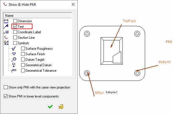
Only the text entities are displayedOnly the text entities are displayed
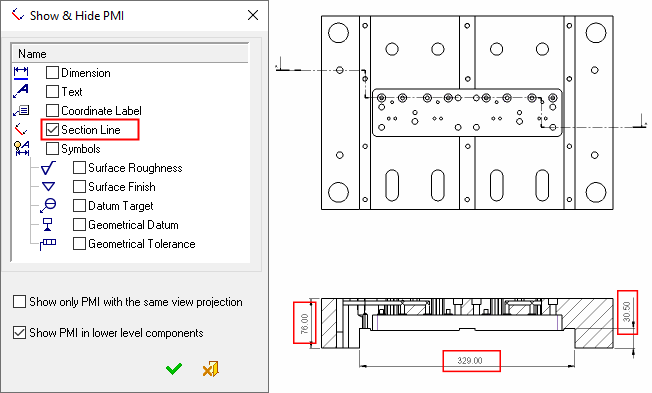
Only the section line entities are displayedOnly the section line entities are displayed
PMI dimensions (created in the model) appear on a section view of a mold plate.
-
Hide specific entities, if required.
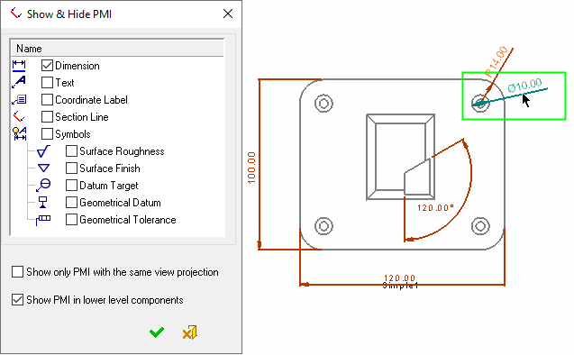
In addition to displaying all of the entities of a type (for example, Dimensions), you can also hide some of the displayed entities. To do this, select the entity checkbox to display all the entities of that type and then pick the specific entities that you wish to hide as shown in the examplesas shown in the examples.
In the picture below, the Dimension checkbox is selected to display all the dimension entities. In addition, a dimension in the top right corner of the view is picked to be hidden.
In the picture below, the two dimensions in the top right corner of the view have been picked to be hidden.
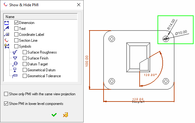
When you press OK ![]() in the dialog, the picked entities (in this case dimensions) are hidden.
in the dialog, the picked entities (in this case dimensions) are hidden.
To re-display the dimensions, invoke the dialog again. The dimensions are displayed in picked mode (as shown above). Unpick (repick) the dimensions if you wish to display them and press OK ![]() in the dialog. The selected dimensions will then be re-displayed in the view.
in the dialog. The selected dimensions will then be re-displayed in the view.
-
Show only PMI with the same view projection: Select this checkbox to only display PMIs created on the same plane as the view (including hidden PMIs in the model).
If this checkbox is not selected (the default option), all PMIs which are within a specified angle with respect to the view plane will be displayed. This angle can be defined in the Drafting PMI Preferences. For example, if this angle is set to 60°, the following PMIs will be displayed:
-
PMIs created on the same plane as the view - (the same PMIs as if the checkbox was selected)
-
PMIs that are not in the view plane but are within 60° of the view plane
-
Show PMI in lower level components: Select this checkbox to display PMIs that were created in lower assembly/part levels of the reference assembly. If the view is created from a part, this option is grayed out.
Notes:
-
Because only the entities that are on the same plane as the view are displayed, if you create a view with a different orientation, other drafting entities may be displayed.
-
When this operation is invoked on Section Views, it displays all PMI data whose reference entities are on the visible side of the section.