|
|
Weld 

Access: Open this function from one of the following locations:
-
Click the
button in the toolbar. -
Select Symbols > GD&T > Weld from the menu bar.
-
Select Drafting Symbols > Weld on the popup menu (right-click the graphics area).
Add a Weld symbol to the drawing.
|
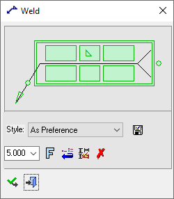
The Weld dialog displays
|
Below is an example of the symbol:
See Entity Overview for a general description. |
Create a Weld symbol to the drawing
-
InvokeInvoke the Weld function.
-
Pick a symbol location or leader position. Picking point on the screen defines the new position of the entity, when no leader is used.(The entity will jump to the picking point).
Note: You can break the segment of the Weld by picking any point on the Weld and dragging it as required.
-
Edit its parameters with the help of the hot spots and tips either directly in the graphic area or on the popup submenu. Change font style
 and character size also, if required.
 -
To complete the current operation and remain in the dialog, press the Apply
 button or <exit><exit>.
To exit the function, press the Close button.
Notes:
-
Right-click the entity itself to access the entity-specific (for editing) and general functions from the popup submenu.
-
Double-click the entity to edit it.
-
See the Symbol notes for additional information.
|