|
|
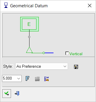
Geometrical Datum 

Access: Open this function from one of the following locations:
-
Click the
button in the toolbar. -
Select Symbols > GD&T > Geometrical Datum from the menu bar.
-
Select Drafting Symbols > Geometrical Datum on the popup menu (right-click the graphics area).
Create a datum reference to attach to a point on the screen or to one of the following:
-
An edge of a planar surface
-
A non-planar feature of size
-
An extension line off the datum feature surface
-
On a size dimension, placed offset to the dimension arrows
-
On a dimension line inline with the dimension arrows
-
On a leader arrow of a size dimension
-
As one half in an open-ended size dimension (inline with arrow)
-
Off a feature control frame that is applied to a surface
-
Off a feature control frame that is applied to a feature of size
|
The Geometrical Datum dialog displays
|
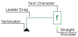
Below is an example of the symbol:
See Entity Overview for a general description. |
Creating a geometrical datum
InvokeInvoke the Geometrical Datum function.
Pick the location of the geometrical datum start point.
Pick a point in the graphic area to position the geometric tolerance and exitexit
Pick a point on the screen to define the new position of the entity (The entity will jump to the picking point). Shoulders are automatically added to non-horizontal geometries but can be added/removed from horizontal geometries by clicking the Straight/Shoulder toggle option in the popup submenu.
Enter a character in the text box.
To complete the current operation and remain in the dialog, press the Apply ![]() button or exitexit.
button or exitexit.
To exit the function, press the Close ![]() button.
button.
Notes:
-
Right-click the entity itself to access the entity-specific (for editing) and general functions from the popup submenu.
-
Double-click the entity to edit it.
-
Creating a PMI geometrical datum symbol (in the Modeling environment) is very similar to creating a geometrical datum symbol in the Drafting environment, even though modeling is a 3D environment and drawing is a 2D environment.
-
See the Symbol notes for additional information.
|