Hole Dimension 
![]()
![]()
Access: Open this function from one of the following locations:
-
From the top menu, select Symbols > Textual > Hole Dimension.
-
From the Symbols toolbar, click the Hole Dimension button.
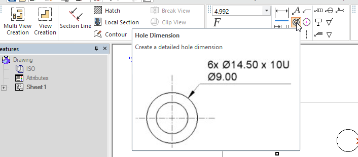
Add labels (which comply to engineering standards) that fully describe the attributes of one or more holes.
These are simple text labels formatted using a template that conforms to the standard (ANSI, JSI, or ISO) applied to the sheet. Hole Dimensions are concise ways to explain four components of a hole in a single dimension: These are diameter, depth, thread, and quantity of similar holes.
|
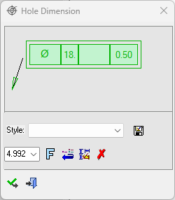
Hole Dimension label text dialog Click on an item in the dialog for a description. See Creating Hole Dimension labels for additional information. |
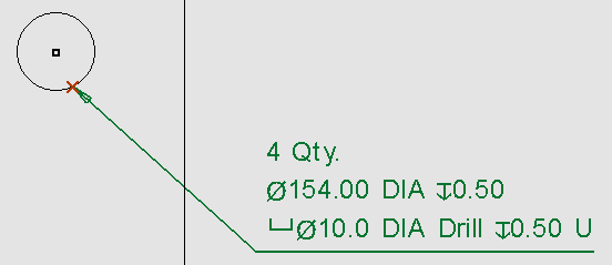
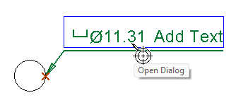
Example Hole Dimension label |
|
|
|

Note: The Hole Dimension capability is only available in Part view.
The feature refers to the settings configured in the Manufacturing Attributes category for certain values such as Diameter Tolerance, Depth Tolerance, and Manufacturing technique; These values are not shown in the dialog but are applied to the dimension label independently. The Ignore Hole setting does not apply, this feature will add dimension labels to any hole that is picked on the drawing.
These settings are also used to assign default values to some Hole Dimension label fields for certain types of hole, such as the depth symbol for blind holes.
Creating Hole Dimension labels
-
InvokeInvoke the Hole Dimension function. A grayed-out dialog is initially displayed.
See the Dimensioning Process for additional information.
-
Pick the entity to be dimensioned—You can only attach a hole dimension to one entity at a time. The Hole Dimension dialog is displayed.
Note: If you select empty space or an item that is not a hole, the function will still display the Hole Dimension dialog, but will not populate any of the fields.
-
Double-click on either the text of the new dimension label or the green area of the Hole Dimension function popup to open the Hole Dimension label text dialog.
Note: The leader line connects to the Hole Dimension label at the correct point for the standard in use, that is the top-most line of the dimension for ANSI and under the dimension for ISO and JIS.
-
The Hole Dimension label text dialog is displayed, and is populated with the details of the selected hole. Update the contents of the Hole Dimension label text dialog with the information about the hole. For more about the individual fields in the dialog, see the Hole Dimension dialog image at the top of this page.
-
When you are satisfied with your changes, close the Hole Dimension label text dialog.
-
Click the Apply button in the Hole Dimension function popup.
-
Click and drag the underline below the dimension text to position the dimension label.