|
|
Hole Safety Distance  : Pane

Access: Open this function from the following location:
-
Select Mold Design > Cooling > Hole Safety Distance from the menu bar.
If analysis data already exists, the Hole Safety Distance Pane is automatically displayed, showing the results of the analysis.
If analysis data does not exist, the Hole Safety Distance function is opened. Set the parameters and click Start Analysis; the Hole Safety Distance Pane is displayed, showing the results of the analysis.
The Hole Safety Distance Pane displays the results of the Hole Safety Distance analysis.
The Hole Safety Distance function identifies design errors that may lead to leakage in molds before manufacturing. Leakage may be caused by corrosion in cooling channels that are not far enough from other cooling channels and holes. The function enables you to analyze and to quickly detect design mistakes and fix the design before actually producing the mold.
If analysis data already exists from the Hole Safety Distance function, the Hole Safety Distance Pane is automatically displayed, showing the results of the analysis.
If analysis data does not exist, the Hole Safety Distance function is opened. Set the parameters and click Start Analysis; the Hole Safety Distance Pane is displayed, showing the results of the analysis.
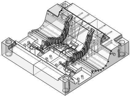
In the Hole Safety Distance Pane, the objects/faces selected for analysis are displayed as transparent (showing the holes) and the Hole Safety Distance dialog is displayed.
|
|
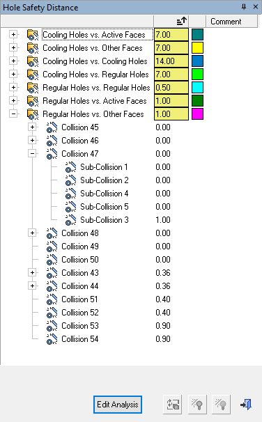
Example of the Hole Safety Distance dialog |
See:
Dialog Structure
The dialog displays the analysis results in a tree structure, with a folder for each one of the collision categories selected for analysis in the Hole Safety Distance function.
|
Cooling Holes vs. Active Faces |
Checks the minimum defined distance of cooling holes against active faces (faces touching the plastic). |
|
Cooling Holes vs. Other Faces |
Checks the minimum defined distance of cooling holes against other faces (anything that is not a hole or active face). |
|
Cooling Holes vs. Cooling Holes |
Checks the minimum defined distance of cooling holes against cooling holes. |
|
Cooling Holes vs. Regular Holes |
Checks the minimum defined distance of cooling holes against regular (non-cooling) holes. |
|
Regular Holes vs. Regular Holes |
Checks the minimum defined distance of regular holes against regular holes. |
|
Regular Holes vs. Active Faces |
Checks the minimum defined distance of regular holes against active faces (faces touching the plastic). |
|
Regular Holes vs. Other Faces |
Checks the minimum defined distance of regular holes against other faces (anything that is not a hole or active face). |
Adjacent to each collision category folder, columns display the Min. Distance value (with a colored background) and the color of the collision category, as set prior to the analysis. The default minimum distance values and color are set in the Preferences. If the distance between the objects being analyzed is less than the Min. Distance value, then these are considered as collisions.
An additional column enables comments to be added.
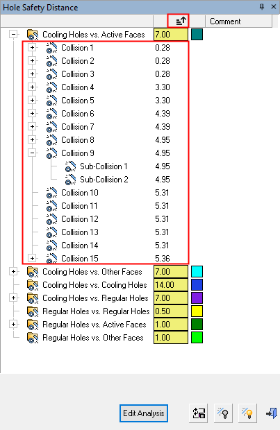
Under each collision category folder, the collisions are displayed as nodes, called Collision 1, Collision 2, Collision 3, etc.
If there are multiple collisions grouped together, these are displayed under the group as individual collisions between 2 items. In this case, the collisions are named Sub-Collision 1, Sub-Collision 2, etc.
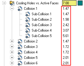
Adjacent to each collision, the distance between the components is displayed. This distance will be ≤ the Min. Distance threshold set for the specific collision category (hence the reason for it to be marked as a collision), as shown below.
|
Adjacent to each collision, the distance between the components is displayed. This distance will be less than the Min. Distance threshold set for the specific collision category (hence the reason for it to be marked as a collision), as shown below. |
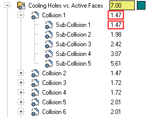
For a group of collisions, the minimum distance in the group is displayed adjacent to the group name. For individual and sub-collisions, the actual distance between the components is displayed. |
|
|
|
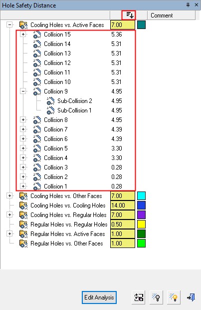
Sorting by Distance
To enable quick recognition of any problematic areas, when the analysis results are displayed in the tree, the items within each folder (and sub items within them) are automatically sorted by distance.
A sort toggle button ( /
/ ) enables you to change the sort order of the Collisions and Sub-Collisions by distance, in ascending or descending order.
Notes:
-
If an item is ignored (or ignored and hidden), it is not included when showing the lowest distance on its parent level.
-
The collision category folders (Cooling Holes vs. Active Faces, etc.) are not sorted.
|
|
|
|
|
|
Dialog Buttons
The following buttons are in the dialog
|
Edit Analysis |
Edit Analysis: Open the Hole Safety Distance function to edit the analysis parameters. Click the Start Analysis button in the function to re-run the analysis. The results of the new analysis are displayed in the Hole Safety Distance Pane. |
|
|
Run an analysis with the same input, for the specific type of analysis (without invoking the Hole Safety Distance function). This is available only if there was a geometrical change on the file since the last analysis. This option is also available as from the popup menu in the dialog. |
|
|
Hide all ignored collisions from the tree. When run from a branch (top level folder), where all its contents are ignored, this hides all the branch contents, except for the branch itself. This is available only if there are visible ignored collisions. This option is also available as from the popup menu in the dialog. |
|
|
Show all ignored collisions. This is be available only if there are hidden ignored collisions. This option is also available as from the popup menu in the dialog. |
|
|
Exit: Exit the operation and close the dialog/task. |
Dialog Operations
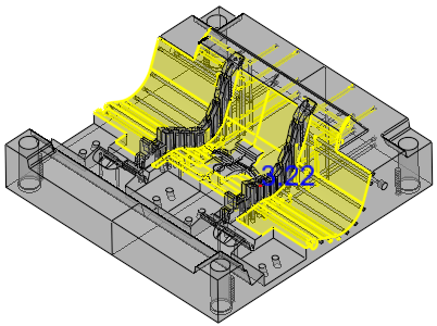
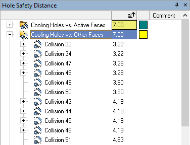
When clicking a branch folder, the faces involved are highlighted and a line and text are shown on the display indicating the smallest distance, for all collisions in the folder that are not ignored.
Example:Example:
| In this example, a folder is selected. The faces involved are highlighted and a line and text are shown on the display indicating the smallest distance in the folder; in this case, that of Collision 33 with a distance of 3.22. | |
|
|
|
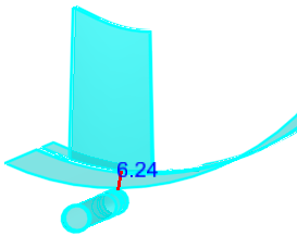
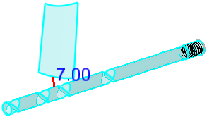
When clicking a group collision that has sub-collisions, the faces involved are highlighted and a line and text are shown on the display indicating the smallest distance in the group, only for sub-collisions that are not ignored (see the Popup Menu below).
Example:Example:
| In this example, a group collision folder is selected. The other faces are hidden (Hide Other - see the Popup Menu below). The faces involved are highlighted and a line and text are shown on the display indicating the smallest distance in the folder; in this case, that of Collisions 7 and 8. | |
|
|
|
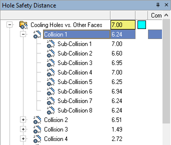
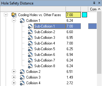
When clicking a collision node, the faces involved are highlighted and a line and text are shown on the display indicating the actual distance.
Example:Example:
| In this example, an individual collision is selected. The other faces are hidden (Hide Other - see the Popup Menu below). The faces involved are highlighted and a line and text are shown on the display indicating the actual distance. | |
|
|
|
When double-clicking a collision node, the faces involved are highlighted and a line and text are shown on the display and the system zooms into the collision area.
Navigate the tree to browse through the collisions, either by using the mouse or by using the up/down arrow keyboard keys.
When a collision view is displayed (and the relevant faces are highlighted), to return to a previous view, press the Previous Hide/Show ![]() button several times, until the required view is displayed.
button several times, until the required view is displayed.
Popup Menu
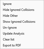
The following popup menu is displayed when right-clicking on any tree node, including multiple selected nodes.
|
Ignore |
Ignore the result. This turns the node and all its content to grayed out. In the case of a branch, this also ignores all its children (including sub-collisions). This option is available only if the selected nodes are not ignored. |
|
Hide Ignored Collisions |
Hide all ignored collisions from the tree. When run from a branch (top level folder), where all its contents are ignored, this hides all the branch contents, except for the branch itself. This is available only if there are visible ignored collisions. This option is also available as a button in the dialog. |
|
Hide Other |
Hide everything except for the selected/highlighted geometry. |
|
Show Ignored Collisions |
Show all ignored collisions. This is be available only if there are hidden ignored collisions. This option is also available as a button in the dialog. |
|
Un-Ignore |
Un-ignore any selected ignored node. This is available only if there selected nodes that are ignored. |
|
Update Analysis |
Run an analysis with the same input, for the specific type of analysis (without invoking the Hole Safety Distance function). This is available only if there was a geometrical change on the file since the last analysis. This option is also available as a button in the dialog. |
|
Clear List |
Remove the entire contents of the branch, except for the branch itself. This is available only from the branch folder level. |
|
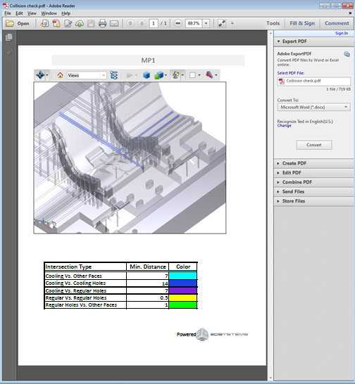
Export to PDF |
Export the analysis results to a 3D PDF file. A save dialog is displayed enabling you to save the PDF file. The PDF files displays the objects selected in the first step of the Hole Safety Distance function. The faces involved in the selected collision(s) are colored in the defined analysis color and the other faces are gray. The PDF also shows all the branch definitions, including the minimum distance and color settings for each branch.
|
|