Long Thin Feature Analysis  : Options and Results

Access: Open this function from the following location:
-
Select Analysis > Main Tools > Long Thin Feature Analysis from the menu bar.
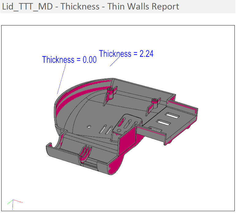
Analyze the geometry and look for thin and long features.
This is an analytical function that detects walls or ribs that are relatively long (with respect to their thickness) and shows the thickness variations using a color-coded display.
Required Step 1 
Pick the body to be analyzed.
Required Step 2 
Set the parameters on which the analysis is to be based and then set the required direction. The following parameters are displayed:
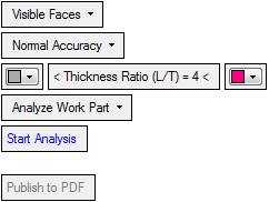
In addition to setting the parameters, a direction arrow is displayed; choose the direction to achieve the best results.
|
Visible Faces |
Define on which faces the operation is to be performed by selecting from the dropdown list. The options include Visible Faces and any QuickSplit faces in the reference object. In addition, if the object has faces with QuickSplit attributes, a list of the relevant attributes is also displayed in the dropdown list. If a QuickSplit set is selected, the arrow direction is not used and the direction will be according to the defined QuickSplit direction. |
||||||||||||||||||
|
Normal Accuracy |
This is a dropdown list to define the accuracy level of the analysis. The available options are Low Accuracy, Normal Accuracy and High Accuracy. This parameter appears for the Wall Thickness and also the Thin Walls options. |
||||||||||||||||||
|
Thickness Ratio |
Set the required thickness ratio between the length (with respect to the arrow direction) and the thickness at any "segment". On either side of this parameter are color options.
|
||||||||||||||||||
|
Analyze Work Part |
Choose the analysis option from the dropdown list. The analysis is made with respect to the arrow direction and "walls" which are not in this direction will not be detected as thin walls. The following analysis options are available:
|
||||||||||||||||||
|
Start Analysis |
Perform the analysis based on the current parameter settings. When analysis is complete, you can move the cursor over areas of the body where color-coded analysis is shown to see the analysis result for each area. Pick a point to attach a label displaying the analysis result at that point.
|
||||||||||||||||||
|
Publish to PDF |
Publish to PDF to create 3D PDF files that include parts and assemblies from Cimatron. When the Publish to PDF button is selected, a dialog is displayed giving you additional controls before the selected entities are exported to PDF. The Publish to PDF button is available after an analysis is run (Start Analysis) and enables you to print the results of the analysis.
|
||||||||||||||||||
When finished, press Exit ![]() in the Feature Guide to complete the function.
in the Feature Guide to complete the function.