|
|
Motion Simulation: Set Permanent Connections 

Access:
Select the Set Permanent Connections
![]() button from the Motion
Simulation dialog.
button from the Motion
Simulation dialog.
The Set Permanent Connections tool enables you to select various geometrical entities to make connections between motion simulation groups. You can define geometrical relations such as coincident, concentric, and tangent that permanently exist between faces of various components.
Permanent connections are useful in cases where a motion simulation group should be directed along a certain trajectory, yet guiding components (such as rails, leading pins, and bushings) do not exist.
No temporary connections will be created between entities involved in a mutual permanent connection. Collision may still occur between other entities of the same components involved and consequently temporary connections may result.
To set permanent connections:
Click the Set Permanent Connections ![]() button in the Motion Simulation dialog.
button in the Motion Simulation dialog.
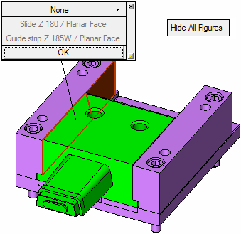
Pick one or two entities and the following screen parameters and parameter Figures (labels) are displayed - see below for parameter descriptions:
The following entities cannot be picked:
-
Two entities from the same motion simulation group.
-
Entities belonging to springs or parts removed from collision detection.
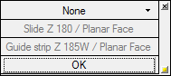
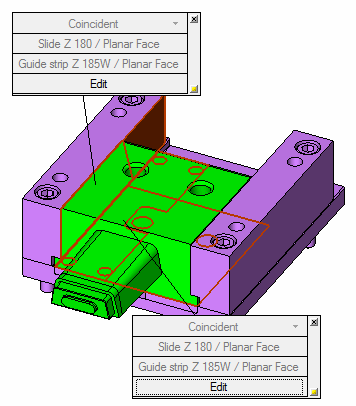
A parameter Figure (label) is displayed for each set of connections and contains connection parameter settings specific to the component to which it is attached. The components holding the entities and the entity type will be indicated as shown above, for example, Slide Z 180 / Planar Face.
Set the connections by defining the parameters.
Parameters
The following screen parameters and parameter Figures (labels) are displayed - see below for parameter descriptions:
Screen Parameters
The screen parameters enable you to hide or show all connection figures.

Figure Parameters
A parameter Figure (label) is displayed for each set of connections and contains connection parameter settings specific to the component to which it is attached.
|
The displayed Figure (label): |
Select the connection type from the following dropdown menu: |
|
|
|
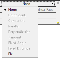
The default is None, meaning that no connection will be created between selected entities. Unless specified, connections are similar to those used in the general assembly environment, except for the Fix connection type - see below.
Available connections will update according to the type of selected entities. For example, if two planar faces are picked, the Concentric option is disabled.
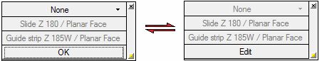
To confirm connection definitions, click OK. The corresponding Figure (label) parameters then becomes disabled until you click Edit:
After approving the connection, select more entities to create more permanent connections.
As long as the tool is invokedinvoked, all connections previously defined are shown, for example:
With each new constraint you create, Cimatron checks the possible over-definition of motion simulation groups, and if necessary, denies the connection.
Unlike the assembly environment, setting a connection does not result in the relocation or re-orientation of a motion simulation group.
Connection types will be disabled if they aren't geometrically possible. For example, coincident connections will be disabled if faces are separated. Parallel connections will be disabled if selected faces are inclined towards each other.
To delete a connection, click the X button in the upper right corner of the Figure. This also clears entity selection.
To hide the Figure, click the ![]() button in the lower right corner.
button in the lower right corner.
Connection entities will still be shown as selected.
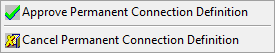
To exit the connection mode, right-click in the display area to display the following approval options and select the appropriate option:
Fix
This type of connection is available for selecting a single planar or cone face, and for selecting an edge, line, or arc.
If a planar face is selected, this indicates that a motion simulation group can only be moved in the selected plane (but not in the direction normal to it), or be rotated on it (i.e. the rotation vector is normal to the selected plane).
If the axis representing entities is selected, this indicates that a motion simulation group can only be moved along the vector represented by the selected entity (line, edge, or cone face axis), or rotated around this vector.
|