PMI Dimension  : Dialog

Access: Open this function from one of the following locations:
-
Click the
button in the toolbar. -
Select Tools > PMI > Dimension from the menu bar.
Create PMI Dimension symbols and assign them to appropriate entities.
|
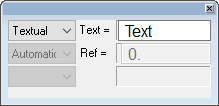
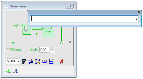
The dialog for the symbol is displayed.
The symbol dialog is initially displayed grayed out until the symbol is positioned in the graphics window.
|
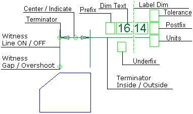
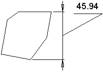
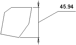
The image below shows an example of the symbol with each element labeled.
The dialog elements for this symbol are described below.
|
|
|
|
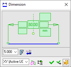
Annotate the symbol either in the dialog or in the graphics window (once the symbol has been positioned).
Edit or re-position a symbol after creation
Double-click the appropriate symbol. The relevant dialog associated with the symbol is displayed. This means that you are now in edit mode.
Edit the symbol elements and/or re-position the symbol as required.
Symbol Elements
|
Change/Indicate |
Toggle to Center the dimension text or to Indicate (by dragging) a location. |
||||||||||||||||||||||||||||
|
Dimension Text |
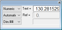
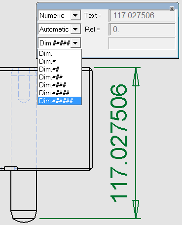
Set the parameters defining the dimension text:
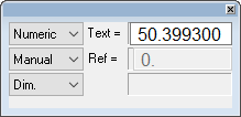
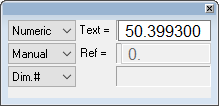
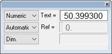
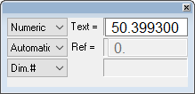
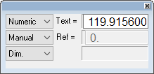
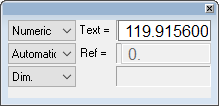
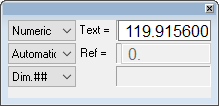
Using Dim. Text:
Dimension Parameter Examples:Dimension Parameter Examples: When selecting Manual, a line appears under the dimension to indicate that it does not reflect the true dimension of the selected entity.
|
||||||||||||||||||||||||||||
|
Label Dim |
Change the position of the dimension leader.
|
||||||||||||||||||||||||||||
|
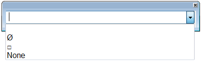
Postfix |
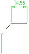
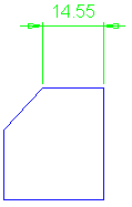
Postfix defines a symbol and/or text that will be displayed after the dimension value. Only the symbols relevant to a particular dimension may be picked. This is defined in the Drawing Standards. See the example in Prefix. |
||||||||||||||||||||||||||||
|
Prefix |
Prefix defines a symbol and/or text that will be displayed before the dimension value. Only the symbols relevant to a particular dimension may be picked. In each of the dimension Prefix, Postfix, and Underfix text fields, a dialog box is displayed enabling you to enter text or to use the dropdown to open the list of previously used text. Text up to 38 characters can be entered. The number of items on each list and also whether the list can be updated is set in the Recently Used Text Preferences.
Notes:
|
||||||||||||||||||||||||||||
|
Leader Drag |
Drag the leader/symbol to a new location on the screen. |
||||||||||||||||||||||||||||
|
Solid/Dashed Line |
Set the font of the leader line. The available values are: Solid, Dashed (default = Solid). This element is only available in the ANSI drawing standard. |
||||||||||||||||||||||||||||
|
Terminator |
Select the required terminator shape from the dropdown list. |
||||||||||||||||||||||||||||
|
Terminator Inside/Outside |
Display the terminators inside or outside the witness lines.
|
||||||||||||||||||||||||||||
|
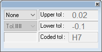
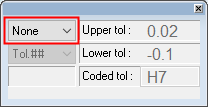
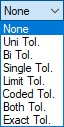
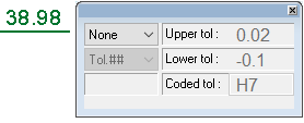
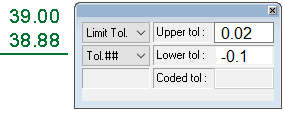
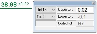
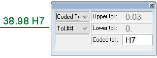
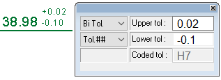
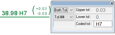
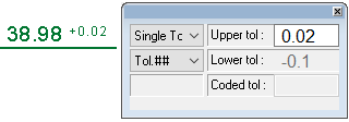
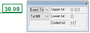
Tolerance |
Set the tolerance values for the dimension. Set the tolerance values:
Example Settings:Example Settings: This dialog is displayed when setting the dimension tolerance in Drafting and PMI functions. The examples below show the PMI Dialogs which do not contain the Tolerance List, which is only displayed for Drafting functions. However, for the specific examples below, the display of the Tolerance List is irrelevant.
|
||||||||||||||||||||||||||||
|
Underfix |
Underfix defines text that is displayed under the dimension value. See the example in Prefix. |
||||||||||||||||||||||||||||
|
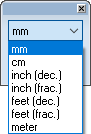
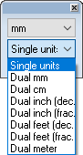
Units |
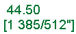
Set the active units of measurement and whether to display dual units, for example in mm and inch. The dual units are displayed in parentheses. Set the units:
Example Settings:Example Settings: Example mm units with dual settings:
|
||||||||||||||||||||||||||||
|
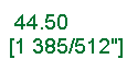
Witness Gap / Overshoot |
Set the Witness Gap and Witness Overshoot values.
The default value can be modified in the Preferences.
|
||||||||||||||||||||||||||||
|
Witness Line ON/OFF |
Display or hide the Witness Line. |


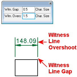
| Witness Gap |
Enter the distance, as a factor of the character size, to be left between witness lines and the corresponding points on the entity being dimensioned. |
| Witness Overshoot |
Enter the distance, as a factor of the character size, that each witness line will extend beyond the dimension line. This extension will be on the side of the dimension line, away from the entity being dimensioned. |
Dialog Buttons
|
|
Set the required font size in the text. Default = 5 |
|
|
Font: Select the font type in which to display the entity. The five most recently used fonts are displayed at the top of the list. |
|
|
Restore Default: Reset all values and settings to the system defaults. |
|
|
Active M-View: Change the projected plane to a preset orientation by selecting the appropriate M-View from the dropdown list. From this point onwards, the projection of this M-View is the default projection for all new entities. PMI M-Views can be added to this list as required. |
|
|
Define Plane: Change the projected plane by picking a planar face, plane, or 3 points to define the active plane. From this point onwards, the projection of this plane is the default projection for all new entities. A plane of any orientation may be defined. |
|
|
Selection Mode (Reference Entities): Pick reference entities (points, edges, etc.) from parts outside the active assembly or part. By default, if an assembly is activated, you can only pick reference entities from sub-assemblies or parts within the active assembly. Similarly, if a part is activated, you can only pick reference entities from the active part. The |
|
|
OK: Accept the changes, perform the operation, and close the current dialog/task. |
|
|
Apply: Accept the changes, perform the operation, and keep the current dialog/task open. |
|
|
Cancel: Cancel all changes and close the dialog/task without saving the settings. |

