Text PMI  : Dialog
![]()
![]()
Access: Open this function from one of the following locations:
-
Click the
button
in the toolbar. -
Select Tools > PMI > Text from the menu bar.
Create PMI Text labels and assign them to appropriate entities.
Creating the PMI Text symbols in the Modeling environment is very similar to creating the Text annotation symbols in the Drafting environment, even though modeling is a 3D environment and drawing is a 2D environment. The main differences are as detailed in PMI & Drafting.
|
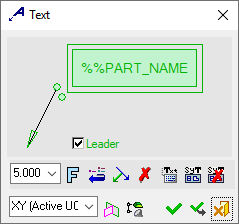
The dialog for the symbol is displayed.
The symbol dialog is initially displayed grayed out until the symbol is positioned in the graphics window.
|
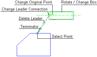
The image below shows an example of the symbol with each element labeled.
The dialog elements for this symbol are described below.
|
|
|
|
Annotate the symbol either in the dialog or in the graphics window (once the symbol has been positioned).
Edit or re-position a symbol after creation
Double-click the appropriate symbol. The relevant dialog associated with the symbol is displayed. This means that you are now in edit mode.
Edit the symbol elements and/or re-position the symbol as required.
Symbol Elements
|
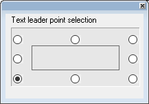
Change Leader Connection/Origin Point |
Define the exit point of the leader by selecting one of the points displayed around the text.
|
||||||
|
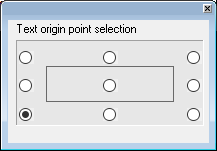
Change Origin Point |
Define the origin point of the text box by selecting one of the points displayed around the text. The following dialog is displayed:
8 points are marked around the text box from which to define the origin point.
|
||||||
|
Leader |
When the Leader checkbox is
OFF |
||||||
|
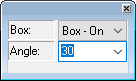
Rotate/Change Box |
Display the entity with/without a box or underline and orientate it at a specified angle.
|
||||||
|
Select Point |
Drag the segment to a new location. |
||||||
|
Terminator |
Select the required terminator shape from the dropdown list. |
||||||
|
With/Without Leader |
Toggle option to display or hide the symbol leader. |
 (unselected),
the next picks will define the text location. When you switch from
(unselected),
the next picks will define the text location. When you switch from  (selected) and the text is already located, a leader will be created at
the next pick.
(selected) and the text is already located, a leader will be created at
the next pick.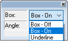
Dialog Buttons
|
|
Set the required font size in the text. Default = 5 Set the required font size in the text. Default = 5 |
||||
|
|
Font: Select the font type in which to display the entity. The five most recently used fonts are displayed at the top of the list. |
||||
|
|
Restore Default: Reset all values and settings to the system defaults. |
||||
|
|
Branch Leader: Add additional leaders to the annotation.
|
||||
|
|
Delete Point: Delete the current entity from the annotation. |
||||
|
|
Create/edit the text in the Text Editor dialog. |
||||
|
|
Attach the Symbolic Text. The field name will be updated. |
||||
|
|
Detach the Symbolic Text. The field name will no longer be updated and cannot be reattached later. |
||||
|
|
Active M-View: Change the projected plane to a preset orientation by selecting the appropriate M-View from the dropdown list. From this point onwards, the projection of this M-View is the default projection for all new entities. PMI M-Views can be added to this list as required. |
||||
|
|
Define Plane: Change the projected plane by picking a planar face, plane, or 3 points to define the active plane. From this point onwards, the projection of this plane is the default projection for all new entities. A plane of any orientation may be defined. |
||||
|
|
Selection Mode (Reference Entities): Pick reference entities (points, edges, etc.) from parts outside the active assembly or part. By default, if an assembly is activated, you can only pick reference entities from sub-assemblies or parts within the active assembly. Similarly, if a part is activated, you can only pick reference entities from the active part. The |
||||
|
|
OK: Accept the changes, perform the operation, and close the current dialog/task. |
||||
|
|
Apply: Accept the changes, perform the operation, and keep the current dialog/task open. |
||||
|
|
Cancel: Cancel all changes and close the dialog/task without saving the settings. |