|
|
Horizontal Machining Expansion: Parameters
These parameters appear in the Horizontal Machining Expansion table and enable the milling of overlaps and extensions on horizontal regions when finish milling with a parallel strategy.
The system will automatically identify the inner and outer boundaries, and you can specify how you would like the toolpath to extend past them. Air Extensions are used when you want a smooth transition off the part or over open holes. Using this option eliminates the need to manually build extra surface extensions. Surface Overlap is another type of toolpath expansion where the toolpath will run a short distance onto the neighboring surfaces, to provide a good overlap between different cuts.
Overlaps and extensions are used to improve the surface finish result, especially when machining adjacent local areas on the part. The system automatically extends toolpath motions in the required areas.
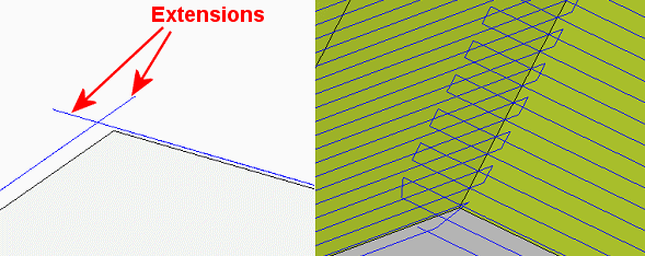
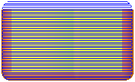
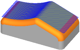
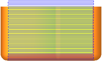
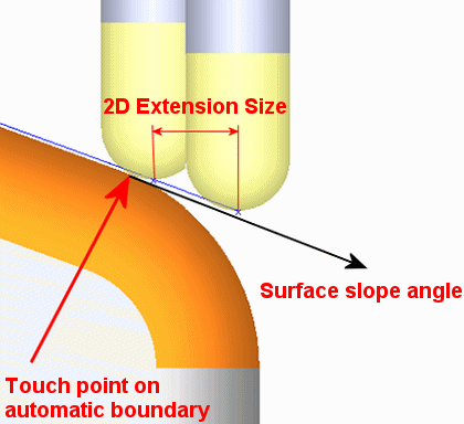
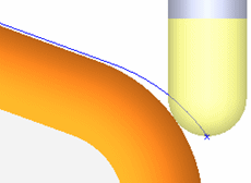
Extensions: Extensions are the creation of extended motions beyond a surface edge. Toolpath extensions serve to improve the sharpness of the edges, ensuring that the part is fully milled and that any surplus stock is removed. In addition, the tool changes direction outside of the part for each pass, preventing any unnecessary marks on the part. When there are gaps in the part, the air extension facilitates smooth transitioning of the tool across these areas without needing to cap the gaps. An extension is straight motion created along the face slope angle, which is measured on the automatic boundary at the relevant point.
Example:Example:
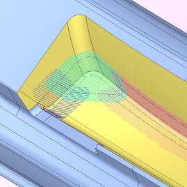
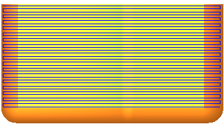
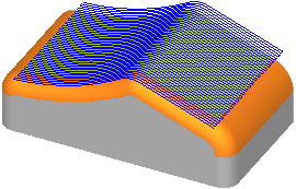
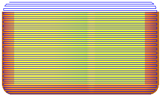
Overlap: Overlap is required to ensure quality machining at the point at which differing toolpaths meet.
Example:Example:
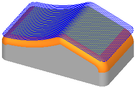
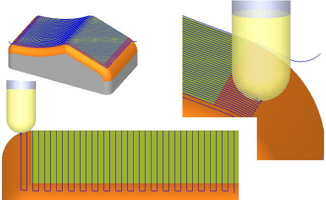
In the example below, the yellow area is milled with three overlapping toolpaths, each with its own orientation. Note that the toolpaths didn’t require manual contour definition of boundaries.
Important: Automatic Boundaries and the exact location of the relevant edges are essential for the prevention of Waterfall motions and also for the Horizontal Machining Expansion calculations (for overlaps and extensions). Horizontal Machining Expansion is created ONLY where Automatic Boundaries exist.
The following parameters appear in the Horizontal Machining Expansion table (the appearance of a parameter in the table is dependent upon the procedure you have selected):
|
Air Extension Direction |
Select the direction of the air extension from the dropdown list of following options:
|
||||||||||||||||||
|
Air Extension |
Set the air extension size. This is a 2D dimension and is measured between the locations of the tool tip, when the tool touches the automatic boundary, to the tool tip at the end of the extension.
|
||||||||||||||||||
|
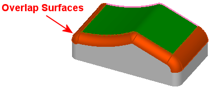
Surface Overlap |
Set the surface overlap size. Overlap Surfaces need to be defined first.
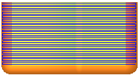
The execution result will show some overlapping motions on the surrounding fillet faces which were selected as Overlap Surfaces. In the example below, there are no extensions or 'waterfall' motions on the far edge. Note that the overlap distance is measured as a 2D distance, the same as with the Air Extension distance.
|
Notes:
-
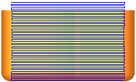
Air Extension and Surface Overlap set together: Air Extension and Overlapping cannot occur together on the same boundary. In such a case, overlapping prevails and is the only one which is created.
In the example below, Air Extension = 10 and Surface Overlap = 5. The result is that the extension was created only on the far free boundary, which does not have an adjacent overlapping face.
Example:Example: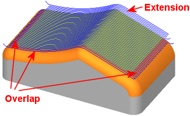
-
Air Extension, Surface Overlap and Margin Offset set together: When Air Extension and Overlapping are set in addition to Margin Offset (Tool Trajectory table in relevant procedures), the air extensions ignore the Margin Offset, however, the overlaps retreat by the size of the Margin Offset.
Example:Example: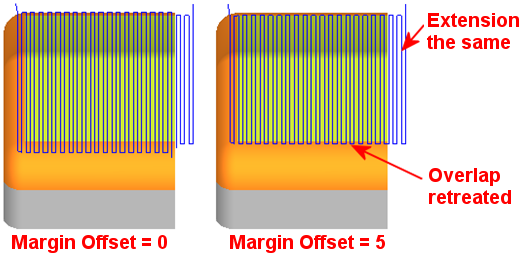
|