|
|
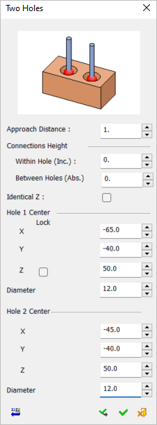
Measurement Cycle: IPM 2 Holes
Measure the coordinates of two holes.
The Two Holes Measurement dialog is displayed below. Select two holes to automatically enter their coordinates or enter the coordinates manually.
|
Cycle Selection > |
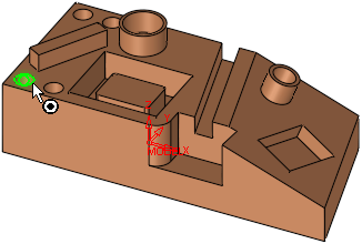
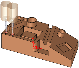
When a location is selected (based on the default options in the Selection Filter), a probe is displayed at the defined measurement point(s). |
|
|
|
|
|
See:
Cycle selection parameters
Lock options
Measurement Cycle dialog buttons
Note: Measuring a geometric feature which is not aligned with the main directions may be problematic for some measuring systems. In others, it is handled by changing the UCS (coordinate system of the working plane) for the specific procedure (as is done for 3+2X milling operations). Note that the dimensions are given according to the active UCS.
Cycle selection parameters
|
Approach Distance |
The size of the measuring motion, which determines how far the probe will be positioned away from the measured point. |
||||
|
Connections Height |
Set the following connection height options – one for within holes (incremental) and one for between holes (absolute).
|
||||
|
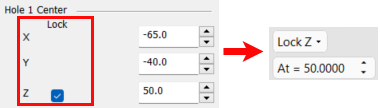
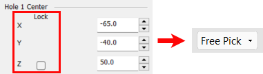
Hole x Center |
The combination of the above parameters defines the measurement values of the following parameters:
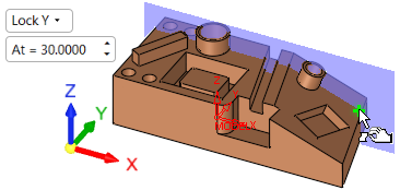
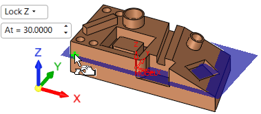
These coordinates may be entered manually or edited manually after the entity selection. In either case, the position of the probe is also updated. Coordinate Lock option This option allows you to lock the Hole 1 Center Z coordinate from the Two Holes measurement dialog. When ON (selected), the screen parameters in the Graphic Pane automatically display the Lock Z option along with its corresponding value. In addition, a BLUE plane appears. The At = screen parameter enables you to move the plane to the required position; selection will only be available on that plane. If the value of the coordinate is changed, the screen parameter and blue plane will change accordingly.
When OFF (unselected), the screen parameter defaults to the Free Pick option and the coordinate values do not change.
|
Lock options
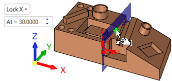
Screen parameters are displayed to specify the lock options to display a plane on the selected lock axis and limit selection to that plane only.
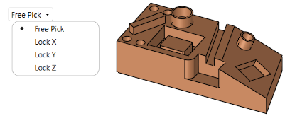
When a lock option is selected (not free), an adjacent parameter value enables you to move the plane to the required position (selection will only be available on that plane).
|
Free Pick enables selection with no plane limits |
Selection is only available on the Lock X plane |
|
|
|
|
Selection is only available on the Lock Y plane |
Selection is only available on the Lock Z plane |
|
|
|
Measurement Cycle dialog buttons
The following buttons appear in the measurement dialog.
|
Exit: Exit the operation and close the dialog/task. |
|
|
Reset: Reset all values and settings to the system defaults. |
|
|
|
Apply: Accept the changes, perform the operation, and keep the current dialog/task open. This button appears only when invoking the measurement cycle from the On Machine Inspection procedure. |
|
OK: Accept the changes, perform the operation, and close the current dialog/task. |
|
|
Cancel: Cancel all changes and close the dialog/task without saving the settings. |
|