Measurement  > On Machine Inspection
![]()
![]()
Access:
-
For Technology, choose Measurement as the main selection and On Machine Inspection as the subselection.
Enable the programming of multiple probing measurements at the end of machining while the part is still on the CNC machine, automatically generating a Quality Assurance (QA) report.
The Measurement procedures are an integrated solution to On Machine Measurement. This means that the system utilizes the CNC machines not only to mill the part, but also to use probes to measure the machining result.
Multiple measurement cycles can be defined in one procedure. The output from this procedure can be a report.
This procedure has one active UCS, which is shared by all its measuring cycles. If one or more features needs to be measured in a different orientation, a separate On Machine Inspection procedure is required.
A typical On Machine Inspection procedure scenario involves the following:
-
The On Machine Inspection procedure creates measurement motions in Cimatron that are posted to the CNC machine.
-
The measurements are executed on the machine.
-
The measurements results are imported from the CNC controller back to Cimatron and associated with the On Machine Inspection procedure.
-
An inspection report of the measurement results is created.
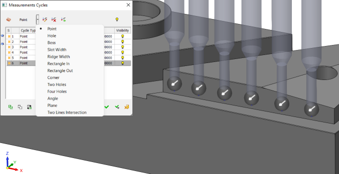
The image below shows multiple measurements taken on the milled part to create an inspection report before the part is removed from the CNC machine. In this case, the Point option is selected in the measurement cycle dialog and 6 points on the slanted wall have been picked. The measurement result is automatically stored in the machine controller for processing and reporting.
The procedure definition consists of the following parts:
-
Procedure definition – Definition of the measurement type to be performed.
-
Procedure action – The action the milling machine will perform with the measurement results.
Notes:
-
When using the Measurement procedures, a measurement tool (probe) is required for the procedure operations. This measurement probe can be defined similar to all other tools in the Cutter Parameters tab of the Cutters and Holders Dialog.
-
Running the Measurement procedures creates tool motions as close as possible to the motions of the measuring probe during "machine" time. These motions are displayed in the Navigator and Simulator, and you can step through them like all other tool motions. However, since in most cases the output from such a procedure to the machine is not a set of motions but a special cycle or a macro call, the true nature of the motions is actually determined on the machine itself, according to the way it was programmed. There are also some differences between the different controls. What is shown in Cimatron are motions that best represent the nature of the different cycles.
How to create this procedure
See Creating a Procedure or Typical Scenario for additional information.
For Technology, choose Measurement as the main selection and On Machine Inspection as the subselection.
Choose the appropriate measurement probe.
Set the Geometry parameters.
Define the following Motion Parameters:
Define the Machine Parameters.
When finished, you can choose from the following Work Mode Dialog buttons:
Note: These options are also available on the Procedure popup submenu.
If Save & Calculate is selected, the Process Manager displays the transformation procedure and indicates which source procedures participated in the transformation and whether they were merged into the transformation.