|
|
Tool Trajectory: Automated Drill > Internal Thread Milling
The Tool Trajectory - Automated Drill parameters are displayed. Depending on the Drill Type you have selected (in the Tool Trajectory table), some parameters may be displayed and others may not be available.
See: Automated Drill Parameters for additional parameter explanations.
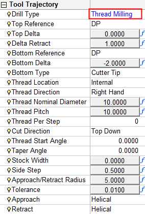
Thread Milling technology can be applied within the Automated Drill procedure by selecting Drill Type = Thread Milling.
The Tool Trajectory - Automated Drill (Thread Milling) parameters are displayed:
|
|
The automated drill parameters specific to the Thread Milling option are explained below. For GPP: For GPP2: As a result of this, some of the Thread parameters may not influence the machining. |
|
Thread Nominal Diameter |
The nominal diameter of the thread. |
||||||
|
Thread Pitch |
The thread pitch. Pitch is the distance between 2 consecutive threads. Thread Pitch example:
|
||||||
|
Thread Per Step |
The number of thread revolutions by which the cutter is shifted along its axis. Cutter examples:
|
||||||
|
Up Cut |
Start the thread milling from the bottom up. |
||||||
|
Thread Start Angle |
Angle at which the thread milling starts. |

For Cimatron Providers:For Cimatron Providers:
The following example shows how to set these parameters for the Cycle 262 (Thread Milling) of the Heidenhain iTNC 530 controller:
Check the GPP parameter CYCLE_SUB (GPP format seqfm). If the value of this parameter is 14, this means that it is a thread milling cycle.
The full lists of Thread Milling parameters are available in the GPP > Block: CYCLE and also the GPP2 > Block: CYCLE.
|
Number |
Name |
Details |
GPP Name |
GPP Format |
||||||
|
{Q335} |
Nominal Diameter |
Relevant only for thread cycle (CYCLE_SUB is 14) |
TRD_NOMD |
1 (COORDINATES) |
||||||
|
{Q239} |
Thread Pitch |
Relevant only for thread cycle (CYCLE_SUB is 14) Thread Pitch example:Thread Pitch example:
|
TRD_PITCH |
1 (COORDINATES) |
||||||
|
{Q355} |
Threads per Step |
The number of thread revolutions by which the cutter is shifted along its axis. Cutter examples:Cutter examples:
|
TRD_STEP |
6 (SEQUENCING) |
||||||
|
{Q253} |
Approach Feed |
Relevant only to thread cycle (CYCLE_SUB is 14). |
TRD_APRFED |
18 (REAL) |
||||||
|
{Q351} |
Climb or Up Cut |
Cut direction, defined as follows: |
TRD_CLIMB |
6 (SEQUENCING) |
||||||
|
{Q200} |
Setup Clearance |
Real, unit dependent, > -9999 |
||||||||
|
{Q201} |
Thread Depth |
Real, unit dependent, > -9999 |
||||||||
|
{Q203} |
Work piece surface coordinates |
Real, unit dependent, > -9999 |
||||||||
|
{Q204} |
2nd setup clearance |
Real, unit dependent, > -9999 |
||||||||
|
{Q207} |
Feed rate for milling |
Real, unit dependent, > -9999 |
||||||||
|
None |
Start angle |
Relevant only for thread cycle (CYCLE_SUB is 14) |
TRD_STRANG |
2 (ANGLES) |
|