|
|
Automated Drill: Tool Trajectory Parameters
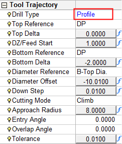
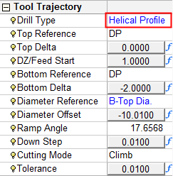
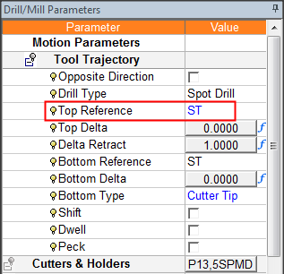
The Tool Trajectory - Automated Drill parameters are displayed. Depending on the Drill Type you have selected (in the Tool Trajectory table), some parameters may be displayed and others may not be available.
Numerical formulas can be used for a number of Automated Drill parameters, for example; Top Delta, Delta Retract and Bottom Delta. See Formula Expressions for additional information regarding the formulas.
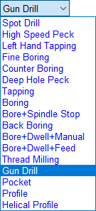
The Automated Drill parameters are explained below. Specific parameters are displayed for the following Drill Types:
|
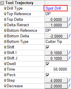
Spot Drill |
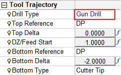
Gun Drill |
||
|
|
|
See the additional Gun Drill parameters in the Machine Parameters Table. |
|
|
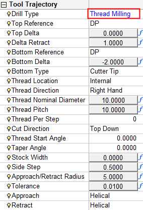
Helical Profile |
|||
|
|
|
|
General Automated Drill Parameter explanations:
Changes to the parameter settings here, also change the displayed value of the relevant parameters in the Cutter Sequence Data table.
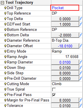
See Internal Thread Milling and Pocket, Profile, Helical Profile for related parameter explanations.
|
Opposite Direction
|
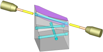
Select the Opposite Direction checkbox to enable drilling both sides of a through hole, using only one sequence. The image below shows two drills positioned on both sides of the through gun drill hole, executed in one sequence.
The ability to drill a hole from two sides (in a single procedure) is dependent on the following conditions: The hole must be a Through hole (not Blind). The machine can access it from both sides. This is dependent on the Max Inclination Angle and the access above each side of the hole. If the angle is set such that a through hole can be drilled from both sides, then the Opposite Direction option is available. When the Opposite Direction checkbox is selected, pick the drilling reference points to reflect the opposite direction. For example, in the image on the left, to milling the C segment, set "Top Reference" as C and "Bottom Reference" as B. Notes:
|
||||||||||
|
Drill Type |
A dropdown list with the following options:
|
||||||||||
|
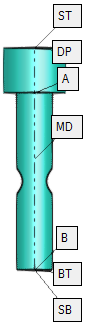
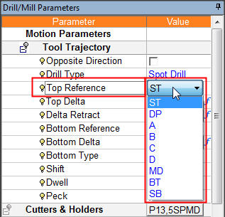
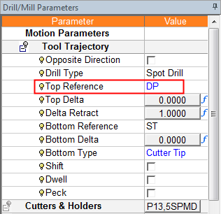
Top Reference |
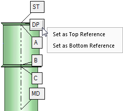
A reference anchor to the drill start point. This reference point can be set in the following ways: Graphically: Right-click a reference point in the graphics area and select an option from the list to define the point as either Set as Top Reference or Set as Bottom Reference. Dropdown List: Select the reference point from the adjacent dropdown list containing the anchors. The default anchor is DP.
The procedure for setting the Top Reference and Bottom Reference points is identical. |
||||||||||
|
Top Delta |
Delta from the Top Reference to the actual point were rapid motion changes to feed. See Using the Cutter Preview. |
||||||||||
|
Delta Retract |
The incremental distance above the drill reference point where the cutter motion changes from the Rapid Feed rate to the Feed rate during the approach. |
||||||||||
|
Bottom Reference |
A reference anchor to the drill end point. The procedure for setting the Top Reference and Bottom Reference points is identical. See the explanation for Top Reference, above. |
||||||||||
|
Bottom Delta |
Delta from the Bottom Reference to the actual point were the drill ends. See Using the Cutter Preview. |
||||||||||
|
Bottom Type |
A geometrical definition to calculate the actual tip location at the bottom. This is a dropdown list containing the following options: Cutter Tip, Full Diameter and Chamfer Diameter. If Chamfer Diameter is selected, the Chamfer Diameter parameter is displayed:
|
||||||||||
|
Shift |
This is the same as the Shift parameter for normal Drill operations. |
||||||||||
|
Dwell |
This is the same as the Dwell parameter for normal Drill operations. |
||||||||||
|
Peck |
This is the same as the Peck parameter for normal Drill operations. |
||||||||||
|