Element Milling Order

Define the milling order of the transformation elements.

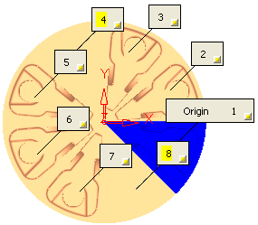
In the example below, the labels clearly define the origin point and the milling order of the transformation elements.
The following options are available in a dropdown list:

Definition

The milling order is defined by the order in which you selected the transformation elements.
For example:For example:


Manually

Manually define the milling order of the transformation elements. The following parameter is displayed.

Manually Ordered Definition

Press the button in this parameter row to initiate the manual interaction.
For example:For example:

In the graphics area, select the required destination label and change the milling order. This automatically updates the milling order of all subsequent destination labels.
For example:For example:

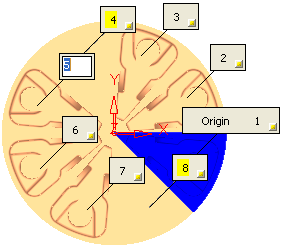
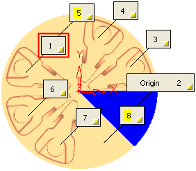
In the example below, there are 8 destination labels, in this case labeled by Definition. Select the required label and enter the new milling order.

In this example, changing label 5 to 1, automatically changes the milling order of affected labels.

Note: Right-click to display a popup menu enabling you to hide all destination labels or to hide/show selected labels.

When  finished, press one of the following approval options (these options are initially grayed out):

OK: Accept the changes, perform the operation and close the current dialog/task.

Apply: Accept the changes, perform the operation and keep the current dialog/task open.

Cancel: Cancel all changes and close the current dialog/task without saving the settings.


Prime X

Set the initial milling direction and, if the direction is either X or Y, select the Array Milling Order; Bidir (Bidirectional) or Unidir (Unidirectional).

Prime Y

Prime Z

Note: For additional information on labels, see the description of Transformation element labels.

Some functionality may be dependent on the product package. Contact your Reseller if you require a license.