|
|
Transformation
Toolpath transformations provide you with a flexible, easy and optimal way of duplicating NC procedures, including 5-axis milling and drilling operations. The definition of a transformation includes not only its shape (matrix, radial, or mirror), but also the machining order. In addition, the duplicated motions are associated to the original procedures, so that when the original procedures change, all the duplications are updated accordingly.
|
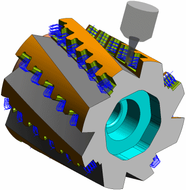
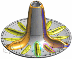
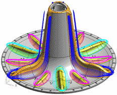
Using toolpath transformations, toolpaths can be copied or moved linearly, radially, or mirrored. Arrays can be defined and controlled with masking capabilities. Transformations speed up the NC programming process and take advantage of motion duplication tools that exist in advanced machine controllers. The image shows how machining an 8-flute insert cutter is quick and simple. In this example, you only need to program 3 out of the 44 pockets using 2-axis, 3-axis and 5-axis operations, as well as drilling, and then transform all these operations, both along the flutes and around the cutter axis. |
Transformation Technologies
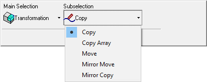
The following Transformation technologies are available in Cimatron:
Transformation procedures |
Copy source procedures to one or more destination transformation elements. |
|
|
Copy source procedures to either a radial or rectangular array of transformation elements. |
||
|
Copy source procedures about a mirroring entity to a destination transformation element. |
||
|
Move source procedures about a mirroring entity to a destination transformation element. |
||
|
Move source procedures to one or more destination transformation elements. |
||
Workflow
The workflow for NC Technologies consists of the following steps:
- Machine Definition. More:More:
This application enables you to construct a machine definition for the Machine Simulator. It enables defining the kinematics tree structure, the axes, and the displayed components of the CNC machine. This enables you to simulate the G-Code motions on a virtual machine that imitates the real machine behavior.
Important! This application is for use by qualified personnel only. Contact your Cimatron Provider or Reseller to get a machine definition for the Machine Simulator.
- NC Setup and Configuration. More:More:
The NC Setup enables you to predefine multiple project-related options in a single place. The NC Setup contains the general data associated with a project, such as the part material, part geometry, machining orientations, fixtures, initial stock, machine name, and post processor. The data defined in the NC Setup is later used as the default for various NC operations. For example, the defined part material is used to set different machining parameters in the cutter definition. The NC Setup parameters can be edited as required.
- Stock definition and update. More:More:
Stock is a 3X procedure used to represent the stock material from which the final part will be produced. Remaining stock is calculated after each procedure so that cutter motions can be optimized upon the current stock status. Stock is also used by the Simulator and Verifier. The remaining stock can be displayed at any time after any executed procedure (the procedure must have a  status flag).
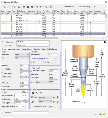
- Cutters and Holders definition. More:More:
Select a cutter for a procedure, define cutters and holders, and set machine and motion parameter defaults for specific cutters.
- Procedure selection. More:More:
Create a Procedure in the active toolpath. A Procedure is a set of cutter movements that conform to a specific machining technology. One or several Procedures can comprise a toolpath.
See Technologies, below.
- Geometry definition. More:More:
The Geometry Parameters define the geometrical entities to be used during the procedure operation.
- Review and output of the toolpath. More:More:
Once the toolpath is created and the procedure has been executed, perform operations on the toolpath to display and analyze the toolpath or edit cutter motions (Navigator, Global Filter, Motion Editor).
The Machining Simulation tools offer a combined environment for machining simulation that includes the following capabilities: material removal simulation, machine simulation, and verifier. These tools enable you to simulate and verify your NC toolpaths and procedures before implementing them on the shop floor.
- Report. More:More:
The NC Report is a file that provides various information about a set of selected procedures. This information includes details about the project and provider, as well as toolpaths, procedures (including multi-cutter information), and parameters.
A Cimatron Post Processor is a program that translates Cimatron NC (Numerical Control) data (toolpaths and procedures) into specific CNCCNC machine tool commands (machine code). These commands are known as Posts or G-Code programs (see the Glossary for additional information on G-Code).
Important: This application is for the use of qualified personnel only. Contact your Cimatron Provider or Reseller to create the appropriate G-Code.
Features Common to all Transformation Procedures
Automatic Update of Remaining Stock of Transformed Procedures
Optimize Cutter Order among Transformed Procedures
Control of Transformation Display and Simulation
Smart Support of Transformations in Post-Processors
Show/Hide the Destination Labels
Automatic Update of Remaining Stock of Transformed Procedures
The transformation operation not only shows the new locations of the transformed toolpath, but also maintains the stock status and updates it. This means that any future operation using the stock on the transformed location(s) will work as if a standard NC operation was performed in this location.
For example:For example:
|
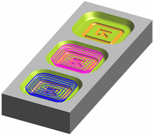
The image below shows rough cutting of two cavities. The blue motions are the original Rough and the purple motions are the Transformation. |
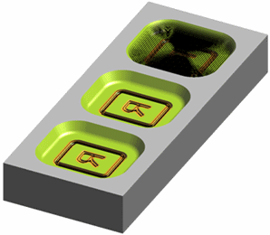
This image shows the motions generated by a 2nd Rough operation (black motions). In the left and center cavities, the 2nd Rough recognizes the stock removed by the 1st rough and also its transformation (so only the slots are machined), while in the right cavity, the operation acts like a 1st Rough. |
|
|
|
Optimize Cutter Order among Transformed Procedures
The toolpath resulting from a Transformation can be optimized to reduce the number of tool changes, to minimize the machine axis rotations or according to the original programming sequence.
For example:For example:
|
The image below shows the original Drill and Surface Finish operations. |
Below is a close-up of the image on the left. |
|
|
|
|
The image below shows the first transformation of only the Finish procedure. |
Below is a close-up of the image on the left. |
|
|
|
|
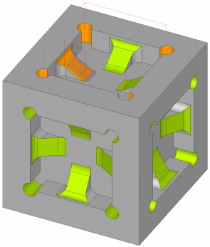
The image on the right shows the second transformation whose input elements are the drill and the result of the first transformation. The resultant G-Code will be sorted by tool, so that the finish operation will start only after the drill operation is completed at all orientations. |
|
Control of Transformation Display and Simulation
To simplify the transformation management, you can control the way the transformations are displayed, independent of the original procedure(s). The display options are:
-
The transformation clearly appears in the NC Process Manager tree.
-
The operations included in the transformation are marked in blue.
The motions resulting from the transformations can be:
-
Hidden or shown as in any other procedure.
-
Can be displayed in any color and pen width.
-
Can be viewed and simulated via the Navigator / Machine Simulator as for any other procedure.
|
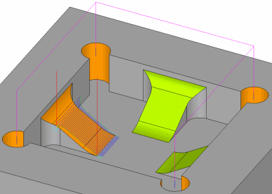
The image below shows 3 original Cleanup operations:
|
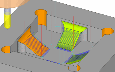
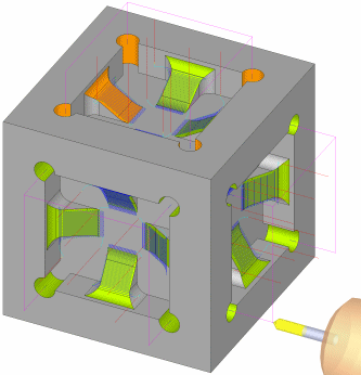
The image below show the original operations and their transformations:
|
|
|
|
Smart Support of Transformations in Post Processors
Transformations are supported for all post processor types and controller levels (both GPP and GPP2 support transformation procedures, but only GPP2 can output the results in subroutines):
-
Basic level: Transformations are fully uploaded and the toolpath is duplicated.
-
Standard level: Uses a single level of the controller's subroutines (available only in GPP2).
-
Advanced level: Uses two levels of the controller's subroutines with loops (available only in GPP2).
Transformation Element Labels
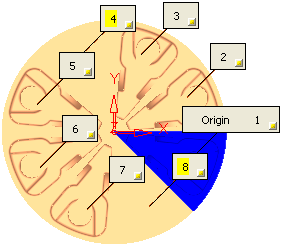
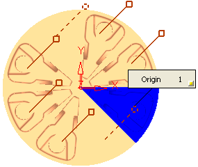
When picking transformation elements, labels are used to mark the origin (source) and target elements, as shown below:
The following types of labels may be displayed (see Label Structure for additional information):
|
|
These labels indicate the origin or source procedures. There is one label of this type in each transformation. This label can appear with or without a number in it. If a number appears in the label, this indicates the milling order of the specific element. This also means that the source procedures have been merged into the transformation and that the source procedures are included in the milling order of the transformation elements. |
|
|
These labels indicate the selected target or destination locations. The number indicates the milling order of the specific transformation element. When the milling order label is highlighted in yellow, as in the example above, this indicates a skipped element where machining does not occur. These destination labels can be shown or hidden, as required. |
|
|
When using the Mirror Move or Mirror Copy Transformation subselections, and picking an entity about which the mirror operation is to be performed, a temporary label is displayed indicating the appropriate operation type. |
Show/Hide the Destination Labels
When the labels are selected, either individually or by box, right-click to display the following popup menu:
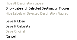
This popup menu enables you to hide or show the labels of selected destinations or to hide all the destination labels. In either case, the label indicating the origin procedures remains displayed, as shown in the examples below:
|
All the destination labels are shown. The skipped elements are highlighted in yellow. |
All the destination labels are hidden. The skipped elements are displayed as dashed lines. |
|
|
|
The popup menu also enables you to save, execute, cancel the procedure.
Label Structure
Each label may contain one of the following symbols:
|
|
This sign signifies the associativity with geometry items. The Transformation procedure is, by default, associative to the source geometry items. However, you can disassociate individual items by toggling the associativity button of the appropriate labels (toggle
|
||||
|
|
The origin procedures or a transformation operation type (for example, Mirror). |
The following control buttons appear in all the labels:
|
|
The X button unselects the entity. |
|
|
The yellow button hides the specific label. |
|
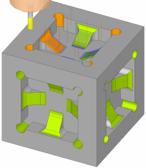
 Transformations are automated tools that increase productivity by moving or creating instances of an already programmed NC operation in seconds, without duplicating the data. A transformation can be applied to single or multiple NC procedures of any type, and even to another transformation.



 to
to  and vice versa).


