Drafting Preferences > General > Dimensions

Access: Invoke this function from one of the following locations:
-
Select the Preferences button
 from the Quick Access Toolbar, or
 -
Select Tools > Main Tools > Preferences from the menu bar.
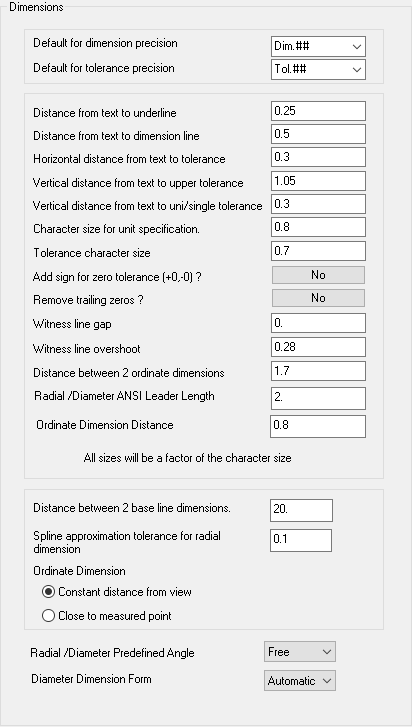
Navigate to Drafting > General > Dimensions.
Set the precision defaults for the dimension tool and tolerance. Define the various definitions for the dimension features.
The Dimensions dialog is displayed.
Interaction
Set the required default dimension values.
|
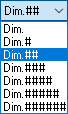
Default for Dimension Precision |
Set the default dimension precision by selecting one from the dropdown listdropdown list.
|
||||||||||||||||
|
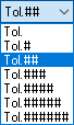
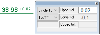
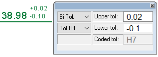
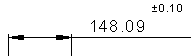
Default for Tolerance Precision |
Set the default tolerance precision by selecting one from the dropdown listdropdown list.
|
||||||||||||||||
|
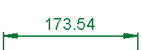
Distance from text to underline |
Set the distance between the dimension text and any underlining. |
||||||||||||||||
|
Distance from text to dimension line |
Set the distance between the dimension text and the dimension line.
|
||||||||||||||||
|
Horizontal distance from text to tolerance |
Set the horizontal distance between the dimension text and the tolerance.
|
||||||||||||||||
|
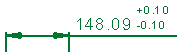
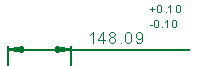
Vertical distance from text to upper tolerance |
Set the vertical distance between the dimension text and the upper tolerance.
|
||||||||||||||||
|
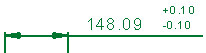
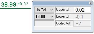
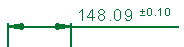
Vertical distance from text to uni/single tolerance |
Set the vertical distance between the dimension text and the uni/single tolerance.
|
||||||||||||||||
|
Character size for unit specification |
Set the default character size for the dimension text. |
||||||||||||||||
|
Tolerance character size |
Set the default character size for the tolerance text. |
||||||||||||||||
|
Add sign for zero tolerance |
Define whether to add a sign for zero tolerances - Yes/No. |
||||||||||||||||
|
Remove trailing zeros |
Define whether to remove trailing zeros from dimensions - Yes/No. |
||||||||||||||||
|
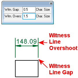
Witness line gap |
Enter the distance, as a factor of the character size, to be left between witness lines and the corresponding points on the entity being dimensioned.
|
||||||||||||||||
|
Witness line overshoot |
Enter the distance, as a factor of the character size, that each witness line will extend beyond the dimension line. This extension will be on the side of the dimension line, away from the entity being dimensioned.
|
||||||||||||||||
|
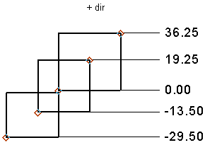
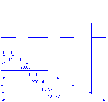
Distance between 2 ordinate dimensions |
Set the default minimum distance between Ordinate Dimensions.
|
||||||||||||||||
|
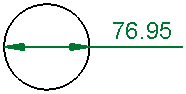
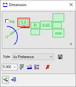
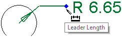
Radial/Diameter ANSI Leader Length |
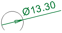
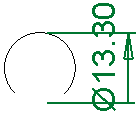
Define the default leader length for Radial and Diameter dimensions. This value can be changed in the Radial and Diameter dimension dialogs, using the Leader Length parameter. Examples:
In the Radial and Diameter dimension dialogs, the Leader Length parameter is only displayed in the ANSI standard and is relevant in the following cases:
The dimension is outside the center (or the arc/circle). The (Diameter) Dimension Form = Linear option is not used. To change the Leader Length, either edit the Leader Length value in the Radial and Diameter dimension dialogs or dynamically drag the dimension itself (in the graphics window) on the Leader Length tooltip.
|
||||||||||||||||
|
Ordinate Dimension Distance |
Set the distance from the view or from the measured point, to where the dimension will be placed. |
||||||||||||||||
|
Distance between 2 base line dimensions |
Set the default minimum distance between Linear Base Line Dimensions.
|
||||||||||||||||
|
Spline approximation tolerance for radial dimension |
Set the spline approximation tolerance for Radial Dimensions. |
||||||||||||||||
|
Ordinate Dimension |
Select the required option to set the position of the dimension in relation to the selected view. |
||||||||||||||||
|
Constant distance from view
|
Position the dimensions a constant distance from the view. This is the default option. |
||||||||||||||||
|
Close to measured point |
Position the dimensions close to the measured point of the view. |
||||||||||||||||
|
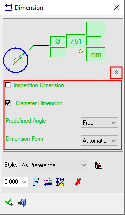
The Radial/Diameter Predefined Angle and Diameter Dimension Form parameters are displayed in the Advanced area of the dialogs.
|
|||||||||||||||||
|
Point to Point Dimension |
Select the appropriate option to set the position of dimensions that are created between two points. |
||||||||||||||||
|
Vertical/Horizontal |
Position dimensions vertically or horizontally between two points. |
||||||||||||||||
|
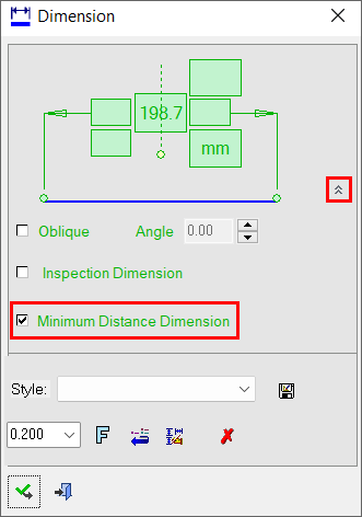
Minimum Distance |
Position dimensions the minimum distance between two points. The Minimum Distance Dimension parameter is displayed in the Advanced area of Dimension dialog (this parameter is displayed for Linear Dimensions only).
|
||||||||||||||||
|
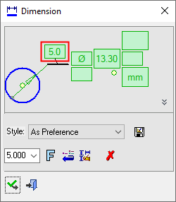
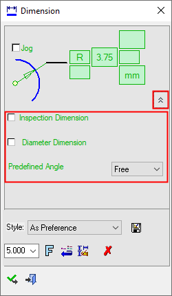
Radial/Diameter Predefined Angle |
This option enables you to preset the angle of the dimension line, as measured from the +X axis of the drawing. You can also choose to dynamically position the dimension line. The following options are available from the dropdown list:
This parameter is used when defining the position of dimension lines in Radial and Diameter dimensions. |
||||||||||||||||
|
Diameter Dimension Form |
This option enables you to change from a Diameter style line that goes through the circle, to a dimension that looks similar to a Linear style dimension. The following options are available from the dropdown list:
This parameter is only displayed when defining the style of Diameter dimensions. |
||||||||||||||||

Select the appropriate approval option.