|
|
NC Preferences > Drill > Tolerances

Access: Invoke this function from one of the following locations:
-
Select the Preferences button
 from the Quick Access Toolbar, or
 -
Select Tools > Main Tools > Preferences from the menu bar.
Navigate to NC > Drill > Tolerances.
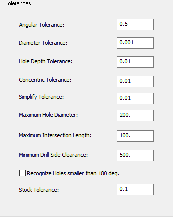
Define the tolerance parameter values that are used to identify holes and to create groups of similar holes for the Automated Drill procedure.
Note: For changes in the Tolerances to take affect, close the Automated Drill procedure and reopen it.
The Tolerances dialog is displayed.
Interaction
Define the default tolerances to identify holes and to create groups of similar holes.
Some of the parameters in this dialog are identical to those in the Table of Holes Preferences.
|
Angular Tolerance |
Determines the maximum angular deviation value of segments within a hole which defines them as part of the same hole. This means that if two faces of the same hole are not on the same axis (within the angular tolerance), they are not defined as being part of the same hole.
|
|
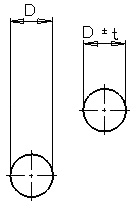
Diameter Tolerance |
Determines the maximum deviation of the diameter value of corresponding segments of different holes which defines them as the same type of hole. This means that if the diameters of corresponding
segments of different holes are not the same (within the diameter tolerance),
they are not defined as the same type
of hole.
|
|
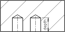
Hole Depth Tolerance |
Determines the maximum depth deviation value of corresponding segments of different holes which defines them as the same type of hole. This means that if the depth of corresponding
segments of different holes are not the same (within the hole depth tolerance),
they are not defined as the same type
of hole.
|
|
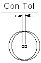
Concentric Tolerance |
Determines the maximum distance between the center points of segments within a hole which defines them as part of the same hole. This means that if two faces of the same hole do not have the same center points (within the concentric tolerance), they are not defined as being part of the same hole.
|
|
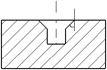
Simplify Tolerance |
Determines the threshold (equal to or below) which a cylinder on a surface is regarded as a hole. This tolerance value will define as a hole, those surfaces that almost define a cylinder. If the difference between the cylinder and the surfaces is equal to or smaller than the tolerance value, a hole is recognized there. |
|
Maximum Hole Diameter |
The maximum diameter the analysis considers to be a permitted hole. |
|
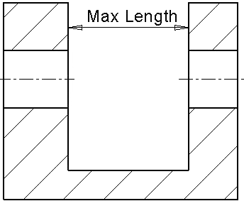
Maximum Intersection Length |
If the distance between two separate holes with the same axis and the same diameter is within this value, they are considered to be the same hole with an intersection segment.
|
|
Minimum Drill Side Clearance |
The minimum clearance required from the hole drill point so that the drill tool can enter and actually drill. When deciding if a drill side is to be used, the clearance above the drill side along the tool axis is calculated. This value is the threshold above which the drill side is available. If a Hole exists with no such clearance, it cannot be drilled and it is rejected by the analysis.
|
|
Recognize holes smaller than 180 degrees |
Select this checkbox to enable the system to recognize holes with a circumference of less than 180 degrees. For example, if a hole is drilled on one of the edges of a cube, half of the hole (or 180 degrees of it) is inside the cube and the other half - outside (in void), but it is still recognized as a hole. However, if the circumference of the hole inside the cube was less than 180 degrees and this parameter is not checked, this entity would not be recognized as a hole. |
|
Stock Tolerance |
Determines the threshold above which the change in the stock height will remove the hole from its group. |
Press the appropriate approval option.
|