|
|
Hole Anchor Points

Access: Open this function from one of the following locations:
Access: Open this function from the following location:
Hole anchor points are displayed when Defining/Modifying a Hole Sequence (a set of faces describing a hole), in either the CAD or NC environments.
-
In the CAD environment: Define/Modify Sequence.
-
In the NC environment: Define/Modify Sequence.
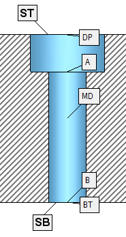
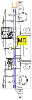
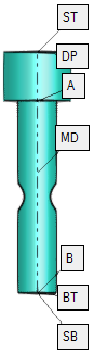
Anchor points are points along the hole axis that are used when defining the parametric drill heights.
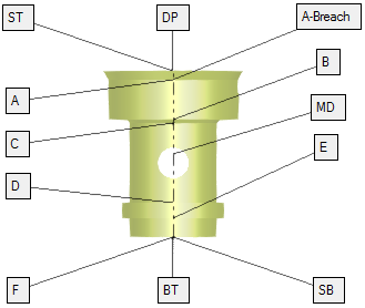
Depending on the type of hole, the number of anchor points signifying each segment (A, B, C, D, etc.) may differ. These anchors are named according to their location - A is the closest to DP, then B, etc.
|
|
|
|
|
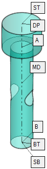
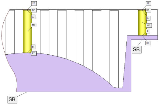
Each anchor point (denoted by a unique letter(s) - unique for each hole) specifies the area from the anchor to the segment above. For example, segment D covers the area from the anchor of segment D up to the anchor of segment C.
Additional anchors define specific points of a hole.
|
ST |
Stock Top: The stock height from the top side. |
|
DP |
Drill Point: The upper point of the geometric hole. |
|
Breach |
Breach: The highest point at which the hole is surrounded by walls. The Breach refers to the top segment of the hole. |
|
MD |
Mid Point: The mid point of length of the hole. This anchor point is used for reference only, as a height for drilling operations, mostly for drilling from both sides. |
|
BT |
Bottom Point: The bottom of a hole. This anchor point enables the same sequence to fit more hole variations from the same hole family. In gun drilling for example, intersections will not require special sequences. |
|
SB |
Stock Bottom: The stock height from the bottom side. |
|
SH |
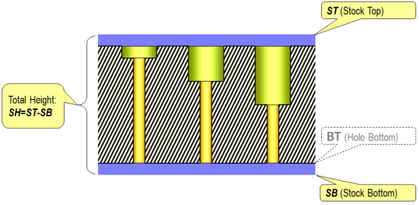
SH: The total depth of the hole as required; either as (SH=ST-BT) or as (SH=ST-SB). |
Note: Anchor points can be assigned to the Top and Bottom Reference parameters in the parameter table, either graphically by right-clicking an anchor and selecting the appropriate parameter, or by a dropdown list of anchor points, in the parameter table.
See:
Anchor Points: Details
Detailed information on specific anchor points:
|
ST |
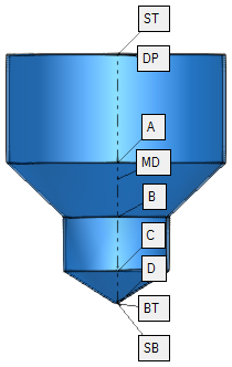
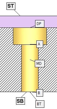
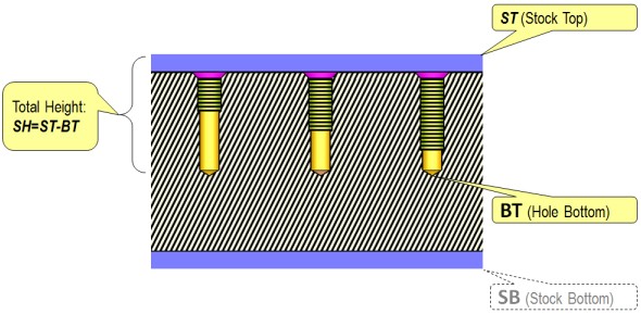
Stock Top: The stock height from the top side. The system recognizes the stock at both the top (ST) and bottom (SB), even if the stock does not exist, including changes to the stock from previous milling operations. As a result, the same sequence can be used to drill plates either with or without stock. In the image below, all three holes can be drilled using the same sequence, even though the ST and/or the SB are different.
ST is available only for 3X Drill if you use the Consider Remaining Stock parameter. If a stock exists and if the Consider Remaining Stock parameter for 3X milling = Yes, or for 4/5X milling = Yes - Bounding Box, the ST anchor point is displayed at the highest stock point, as described above. In the Geometrical Data table, an additional value of ST Height is displayed and if you expand the table you can insert ranges. In the Cutter Sequence Data table (when defining the technological sequence), you can refer to the ST in the Top Reference and Bottom Reference dropdown lists. If the Consider Remaining Stock parameter is No, the previous stock is ignored and the hole starts with the DP (Drill Point) anchor. In this case, ST and DP are displayed at DP. If the Consider Remaining Stock parameter is changed from Yes to No, ST and DP are displayed at ST. If the Consider Remaining Stock parameter is changed from No to Yes, the system checks if there is a certain height above the hole; if so, this is the stock and ST is re-located to the highest stock point. If there is no height above the hole, ST remains at DP. If in 4/5X milling, the Consider Remaining Stock parameter is Yes - Bounding Box, the system checks if there is a certain height above the hole; if so, this is the bounding box model of the stock and ST is re-located to the highest stock point. If there is no height above the hole, ST remains at DP. See SB for the bottom side stock anchor point. |
||||||
|
DP |
Drill Point: The upper point of the geometric hole. |
||||||
|
Breach |
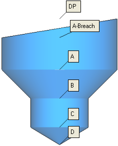
Breach: The highest point at which the hole is surrounded by walls. The Breach refers to the top segment of the hole.
|
||||||
|
MD |
Mid Point: The mid point of length of the hole. This anchor point is used for reference only, as a height for drilling operations, mostly for drilling from both sides. When a hole is a Through Hole it can be drilled from both sides of the part. To help facilitate this possibility, you can program drilling half way through from both sides. You can, for example, program to drill 2mm past the Mid Point from each side. This is particularly useful for gun drilling when holes are being drilled from both sides. As a result, the same sequence will fit more hole variations from the same hole family.
Note: Even if a hole is only drilled to the Mid Point, it is still considered a Drilled Hole in any later Automated Drill procedure. Its constraint is fixed to "N/A" and its value is defined as half the total height (BT). When a group of holes does not contain any holes (only drill points, for example), the MD anchor point is not displayed. This applies in all the relevant places (screen parameters, Geometrical Data table, grid parameters values, etc.). See the parameter Opposite Direction in the Automated Drill Tool Trajectory Table. |
||||||
|
BT |
Bottom Point: The bottom of a hole. This anchor point enables the same sequence to fit more hole variations from the same hole family. In gun drilling for example, intersections will not require special sequences. For an example of its usage, see the first example in SH below. When a group of holes does not contain any hole (only drill points, for example), the BT anchor point is not displayed. This applies in all the relevant places (screen parameters, Geometrical Data table, grid parameters values, etc.). |
||||||
|
SB |
Stock Bottom: The stock height from the bottom side. This point allows the drill to automatically recognize stock at the bottom of the part.
SB is available only for 4/5X procedures, when the Opposite Direction parameter is selected, on a group of holes that is capable of being drilled from both sides (this means that the holes must be through holes, and that the machine must be able to access the holes from both sides). If the parameter is checked, select the reference points to reflect the opposite direction; for example, to mill the C segment of a hole, set Top Reference as C and Bottom Reference as B. See ST for the top side stock anchor point and for additional examples of using ST and SB. |
||||||
|
SH |
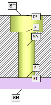
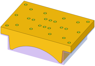
SH: The total depth of the hole as required; either as (SH=ST-BT) or as (SH=ST-SB). This parameter allows you to define the sequence constraint as the distance between the stock at the top (ST) and the bottom point of the hole (BT), or between the stock at the top (ST) and the stock at the bottom (SB). This is especially useful for limiting the total hole height to the length of the drill. See the examples below. Example - (SH=ST-BT)Example - (SH=ST-BT) In the image below, all of the three blind holes can be drilled with the same sequence. Each hole has three segments and the depth of each segment can be limited by a range. SH defines the total depth of the hole (SH=ST-BT) that can also be constrained.
Example - (SH=ST-SB)Example - (SH=ST-SB) In the image below, all of these three through holes can be drilled with the same sequence. Each hole has two segments – the drill hole and counterbore hole, and the depth of each segment can be limited by a range. SH defines the total depth of the hole (SH=ST-SB) that can now also be constrained.
This segment is the total depth of the hole and can be used for constraint and for reference. Its default constraint type is "N/A". When changed from "N/A" to "Range", it will get the following default values:
If the constraint type is changed to "Fix", the value is set to the sum of all nominal heights. |
||||||
Anchor Points: Location
Anchor points, signifying each segment of a hole, are positioned automatically. The automatic location of anchor points is defined by the number of anchor point labels:
|
No. of labels = 1 to 10: |
No. of Labels = 11 to 20: |
No. of Labels ≥ 21: |
|
|
|
|

|