Setting a Direction: Plane and Angle

Access:
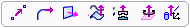
Click the base of the Directional
Arrow to display the toolbar of direction options. Select the
By Angle option ![]() .
.
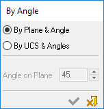
Set a direction by angle using the By Angle > By Plane & Angle option.
|
Demo: Press the button below to view
a short movie demonstrating the function:
|
Practice: Press the button below to open Cimatron with a practice ELT file similar to that used to create the movie (if the relevant feature already exists in the ELT file, you can either edit it or delete it and create a new feature). |
|
|
|

In the example below, the Add Extrude function is to be used to extrude the circle.
|
Extrude the circle. |
By default, the extrude direction is normal to the plane/face of the entity. |
To select another direction, select the arrow base. |
A toolbar of direction options is displayed. For this example, select the By Angle option |
|
|
|
|
|
The By Angle dialog is displayed; select the By Plane & Angle option.
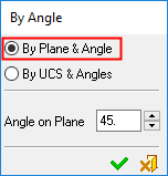
To set the direction vector, select a plane and define the angle.
|
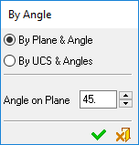
Pick a planar face or plane that is parallel to the desired direction vector. |
A set of section and cross-section (C and S) axes appears. Enter the counter-clockwise angle from the S axis to the desired vector (180 degrees = no change in angle, but a flip in direction). |
||
|
|
|
||
|
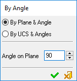
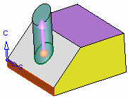
Result: In this case, an angle of 90 degrees from the S axis is set. |
Another view of the image on the left. |
||
|
|
|
|
|
Another Example
|
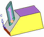
Pick a planar face or plane that is parallel to the desired direction vector. |
A set of section and cross-section (C and S) axes appears. Enter the counter-clockwise angle from the S axis to the desired vector (180 degrees = no change in angle, but a flip in direction). |
In this case, since the vector is pointing the wrong way, click on the arrow body to flip the direction. (The same vector would have been obtained by entering 180 degrees). |
|
|
|
|
|
Result: In this case, an angle of 180 degrees from the S axis is set. |
Another view of the image on the left. |
|
|
|
|