Machine Definition  : Hale Machining Support

Access: Open this function from one of the following locations:
-
Select NC Utilities > Utilities > Machine Definition from the menu bar.
-
Cimatron Control Panel: Select Start > All Programs > Cimatron > Cimatron Control Panel.
Select NC > Machine Definition.
This application enables you to construct a machine definition for the Machine Simulator. It enables defining the kinematics tree structure, the axes, and the displayed components of the CNC machine. This enables you to simulate the G-Code motions on a virtual machine that imitates the real machine behavior.
Important! This application is for use by qualified personnel only. Contact your Cimatron Provider or Reseller to get a machine definition for the Machine Simulator.
Hale Machining is a kind of machining where a haling tool (non-rotational tool) is used for producing a mirror surface finish without the necessity to manually polish the metal after cutting. It is used, for example, for optics molds and parts for lenses, lens array, and Fresnel lens grooves.
Hale machining uses non-revolving cutters that may be round, v-shaped, or square. It uses ultra-sonic vibration to cut the metal.
A 5-Axis Micro-Milling Hale toolpath supports all tool shapes.
Hale Tool Machine Definition
The simulation of Hale Machining in the Machine Simulator is handled as follows:
-
The hale cutter is created as an STL geometry and added to the machine, as any other component.
-
This component is named Hale_Tool<any text>. The name must start with "Hale_Tool" (not case sensitive) and may optionally be followed by any other text.
-
Any component which starts with "Hale_Tool" will be considered as a tool. It will remove material and check for collisions and gouges.
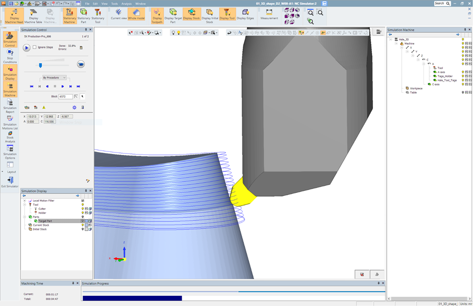
The image below shows hale machining in the machine simulation environment. The non-revolving cutter is recognized as a cutter, removes material, and checks for collisions and gouges against the part like any regular cutter.