Machine Parameters 
![]()
![]()
Access: Open this function from the following location:
-
Click Machine Parameters
in the NC Setup dialog.
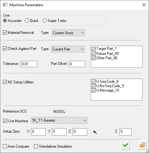
Using the Machine Parameters dialog (in addition to the part, cutter, and holder), you can also view the entire machine and fixtures inside the NC programming environment. You can manually move the machine axes, considering the machine kinematics and travel limits, to an optimal orientation. Once found, an appropriate UCS is defined to be used for programming the procedure(s). In addition, selecting a machine simulator enables you to preview the part in the CNC machine table.
When this operation is usedused, the Machine Parameters dialog is displayed. The Machine Parameters, Machine Preview, and Machining Simulation tools present similar parameters. The Machine Parameters dialog is essentially the lower part of the Machining Simulation dialog with some additional functionality, enabling the selection of the machine and setting machine and simulation parameters.
|
|
Use the Machine Parameters to perform the following tasks.
The Machine Parameters dialog shows the same machine that was defined in the NC Setup, the same Reference UCS, and the same Setup Zero values. All these settings can be changed or initially set if the NC Setup is not in use. |
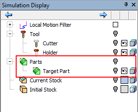
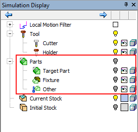
Notes for Current Parts & Utility Procedures
-
When there is more than one NC Setup in the Process Manager:
-
The Utilities from all setups are added to the NC Setup Utilities list of the dialog.
-
For all other parameters (Tolerance, Stock, Part, and so on), the defaults of the first NC Setup are used.
-
-
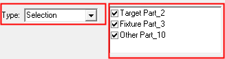
The Current Part list is kept as is, even if the selection of the procedures has changed.
It is updated only if you re-select the option Current Part; in which case, the current list of parts is taken from the current first NC Setup. -
If a Part procedure is added to the NC Setup, it is set as selected (ON
 ) in the Current Part list of the dialog.
 -
If a Utility procedure is added to the NC Setup, it is set as selected (ON
) in the NC Setup Utilities list of the dialog. -
If the Check Against Part checkbox or NC Setup Utilities checkbox is OFF
 , then any new Parts or Utilities are deselected (OFF ), until the Check Against Part checkbox or NC Setup Utilities checkbox is selected as ON .
Simulation dialog parameters
The parameters that are available depend upon which of the following simulator modes you have selected: Standard, Quick, or Super Turbo (for additional information on each mode, click the relevant link).
|
The Accurate and Quick modes are used for the following (depending on the options selected):
The Accurate mode is the most accurate simulation, taking the required amount of time to achieve the high quality results. The Quick mode is a faster simulation with looser tolerances. Quick is the default mode. |
|
|
The Super Turbo mode is used for:
The Super Turbo mode is the fastest simulation with the loosest tolerances; it provides you with an indication of whether there are likely to be any major problems in the material removal process. Note that this mode is only available for 3-axis machining and only for material removal simulation; it cannot be used for machine simulation. |
Machine Parameters dialog parameters
|
Material Removal |
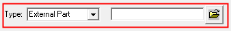
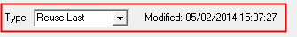
When this checkbox is ON Select the type of stock to be used, from a dropdown list of options.
|
||||||||||||||||||
|
Check Against Part |
When this checkbox is ON Select the type of part to be used, from a dropdown list of options.
See the Notes above for Current Parts & Utility Procedures. |
||||||||||||||||||
|
Tolerance |
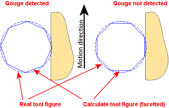
Define the toolpath tolerance for the simulation. This is also used as a threshold for gouge checking as any gouges are displayed in red. The default is 0.01 mm / 0.0004 inch. Note that this tolerance affects a number of things:
The fact that the tool is actually considered as a polygon rather than its true round shape is the same in most simulators. This might cause some detection accuracy issues. Depending of the angle of the polygons and the motion direction in reference to the part geometry, some gouges will not be detected. Note that in reality the calculated representation of the tool is not as coarse as seen in the below image. This image is a schematic representation of the accuracy issues.
|
||||||||||||||||||
|
Part Offset |
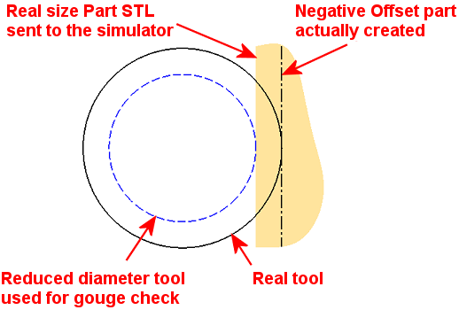
Sets a safety clearance for the collision check between machine components and the part. Define the part offset against which you wish to perform the gouge checking and remaining material reporting. The default is 0 mm / inch. The Part STL file is always created in the exact size it is designed in Cimatron. When an offset other than zero is set, the simulator engine imitates a different Part by changing the tool diameter accordingly.
|
||||||||||||||||||
|
NC Setup Utilities |
When this checkbox is ON Utility procedures may change the configuration of the machine. Therefore, by applying them in the NC Setup Utilities section of the dialog prior to the run, any configuration changes are taken into account. If there are no Utility procedures, the NC Setup Utilities section of the dialog is empty and dimmed. See the Notes above for Current Parts & Utility Procedures. |
||||||||||||||||||
|
Reference UCS |
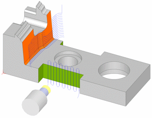
This field displays the settings as defined in the NC Setup; this can be changed if required. Define the Reference UCS on which the current operation is to be based from a dropdown list of all the UCSs in the current ELT file. This Reference UCS enables you to define a different UCS as required; for example, when a different clamping situation is necessary, typically "Machining from TOP" and "Machining from BOTTOM". In the example below, the orange surface will be machined from above and the green area from the side. Because it is machined from another orientation, the green surface toolpath has different motion limits, which are based on its own separate UCS.
The Reference UCS is also important in the posting process where it defines the reference point and reference axes direction for the whole posting process. All other UCS's and tool points are defined relative to the Reference UCS. The Reference UCS is also used by the Setup
Zero.
The default value is the active UCS. |
||||||||||||||||||
|
Machine |
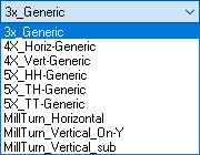
This field displays the name of the machine which is selected for the machining process. If a machine was defined in the NC Setup, the same machine is displayed; however, it is possible to select a different machine. Select the type of CNC machine to be used from a dropdown list of options. For example:
Note: To add CNC machines to the library, contact your Cimatron Provider or Reseller. This field displays the name of the machine which is selected for the machining process as defined in the NC Setup; this can be changed if required. Select the machine to be used, from the dropdown list. |
||||||||||||||||||
|
Setup Zero |
This field displays the settings as defined in the NC Setup; this can be changed if required. The numbers displayed here represent the position of the part (to be machined) on the machining center, relative to a predefined UCS. You can modify the offset values to adjust the part location within the machine envelope, enabling optimal use of the available space. Define the XYZ machine zero in the coordinate system, either by directly entering the XYZ coordinates or by using the adjacent The coordinates are passed to the Post Processor in the BEGINNING OF TAPE block (X_MACH, Y_MACH, Z_MACH).
This definition is needed for Machining Simulation, but also affects the actual G-Code if being used by the specific post processor. Modifying the Reference UCS at any point (or switching between a GPP post processor to a GPP2 post processor) does not affect the numbers. Once calculated (or keyed in), they stay "as is". For GPP2, setting the displayed numbers at (0,0,0) effectively tells GPP2 to ignore them (since it means that the machine zero point is at the REF UCS zero point). This is equivalent to setting M5_USE_MACH (5X machine definition variable) to FALSE inside the post processor. |


The following options appear at the bottom of the dialog.
|
Auto Compare |
When this checkbox is ON |
|
Standalone Simulation |
The simulator is, by default, loaded as an additional application inside the current Cimatron session. When this checkbox is ON There are at least two possible reasons for simulating in standalone mode:
|
Click OK ![]() to activate
to activate