|
|
Symbolic Text
![]()
![]()
Access: Open this function from one of the following locations:
-
Click the
 button in the toolbar.
 -
Select Tools > PMI > Text from the menu bar.
-
Select Symbols > Textual > Text from the menu bar.
-
Select Text on the popup menu (right-click the graphics area).
Using Symbolic Text can help automate common notes on a drawing. The Symbolic Text option allows you to enter a field type (in the format %%<field type>). The field type can be part of a sentence and separated by blanks from other words. It is selected from a list in the Text Editor and is later updated with the corresponding field name. The symbolic text can be added to a View or BOM .
However, not every note that you might need is provided by the system's default attributes. For this reason the <Product_Name> Control Panel has the Attributes Manager utility. Here you can create a new attribute, and if the Update Symbolic Text Table box is checked, the new attribute will also become a new Symbolic Text.
The symbolic text is accessed from the sym_text.csv file in the following folder:
...\ProgramData\Cimatron\Cimatron\\Data\Resource
Note: New attributes are connected to files such as parts or assemblies, and proper use of Symbolic Text requires it be attached to that part or assembly, so the information can be passed down to the Variable Text. However, since the assembly is often not included in every drawing, text that is useful at the project level (such as Job Number), is not passed down and the Symbolic Text has no part to be attached to.
Rather than typing this information over and over into every part attribute, an easier way is to create a dummy part in each project folder, then entering the text (for example Job Number) as an attribute for this part. The geometry for the dummy part can be a tiny object. Place the dummy part into the corner of the drawing, and you can use it as the attachment part for the Symbolic Texts in your frame or views.
Symbolic Text - Example Excel
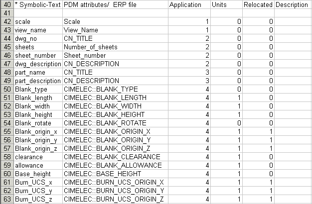
Column Headers
|
Symbolic Text |
Enter the name of the symbolic text from the <Product_Name> Explorer or XML. |
|
PDM Attributes / ERP File |
Enter the name of the attribute. (This column is not translated). |
|
Application |
Select the application from which you want to read the data: |
|
Units |
0 = Not unit-dependent. (Same result for inch and mm). |
|
Relocated |
Only relevant for electrodes. |
|
Description |
Enter notes or description (optional). |
Notes:
-
Text fields are divided by Application into the four groups they describe:
1= View_data, 2 = Drafting, 3 = Part, 4 = Electrode. -
Symbolic text parameters are named so that they can easily be located in the parameter list. For example, symbolic text parameters for sheets in Drafting all start with the word Sheet at the beginning of the parameter name , symbolic text parameters for DieDesign data all start with the word Die at the beginning of the parameter name, and so on .
-
Empty symbolic text fields are not printed or plotted. The empty fields refer to those with the "%%<name>" values displayed. If some fields have visible text and some are empty, only the fields with visible text are printed or plotted.
See Using Symbolic Text for usage examples in Drafting.
|