Measurement Probes 

Access: Open this function from one of the following locations:
The Cutters and Holders dialog (or the minimized version - the Select Only Mode):
-
When not editing or creating a procedure, select NC-Process > Cutters > Cutters from the menu bar or select Cutters
in the NC Guide Toolbar. -
While editing or creating a procedure, use one of the following methods (in both methods, the Select Only Mode is displayed):
-
In the Advanced Mode, click on the cutter name in the Procedure Parameter Table.
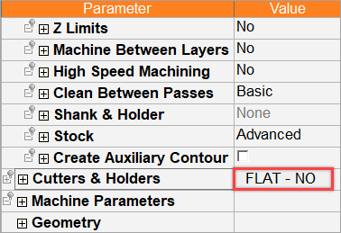
-
In the Wizard Mode, select the cutter button.
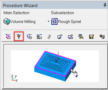
-
-
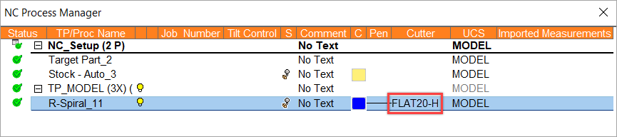
In the Process Manager, click on the cutter name in the procedure row (in this case, the Select Only Mode is displayed).
Cimatron provides the capability to define measurement probes to be used by the Measurement procedures.
Only the In-Process Measurement procedure can select measurement tools; other procedures cannot select them. Once created, a Measurement tool cannot be converted to other types and vice versa.
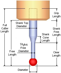
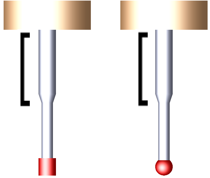
Measurement probes
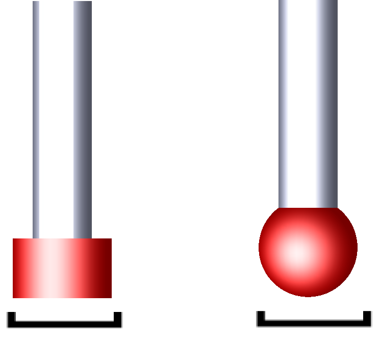
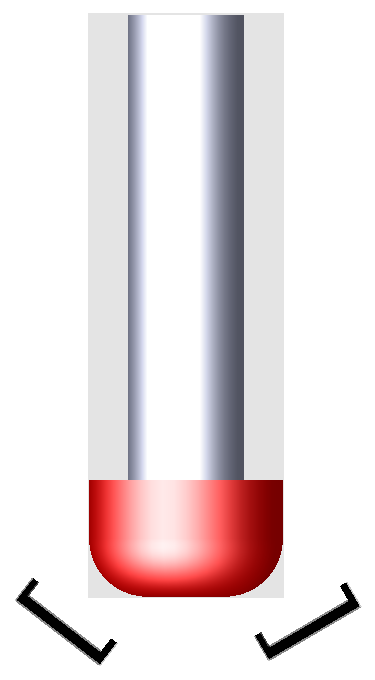
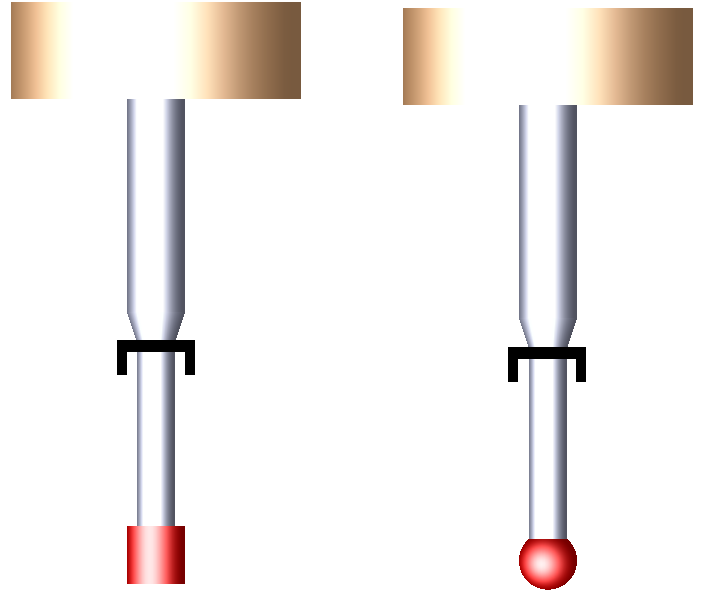
Cimatron supports two types of measurement probes: Ball and Cylinder.
Ball |
Cylinder |
|
|
 |
Cutters and Holders dialog – Cutter tab
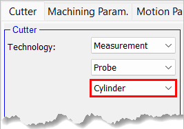
When using the Measurement procedures, a measurement probe is required for the procedure operations. This measurement probe can be defined in the Cutter Parameters tab of the Cutters and Holders dialog.
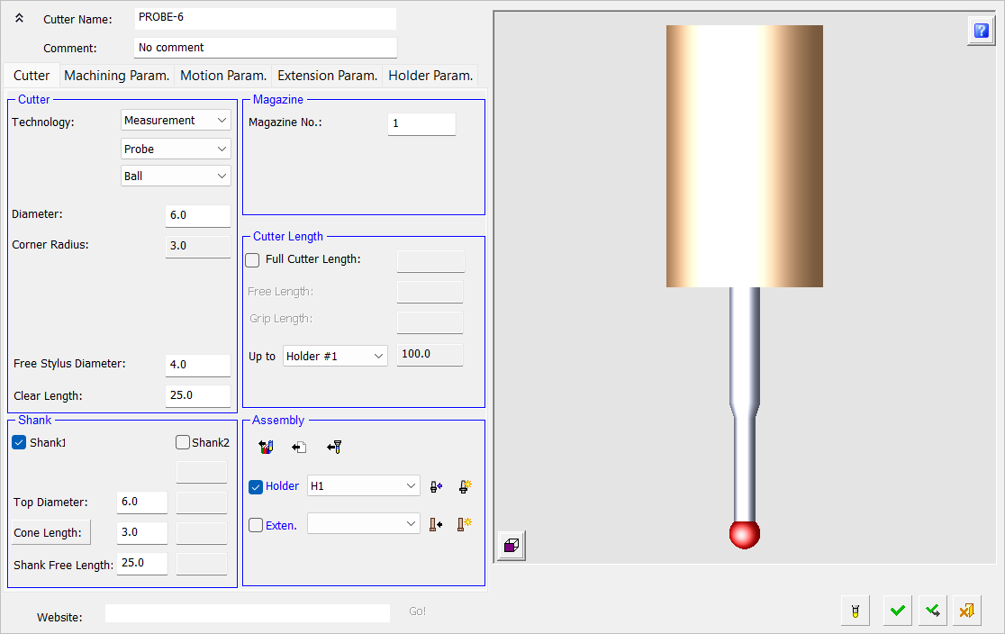
Cutter tab – Measure probe ball
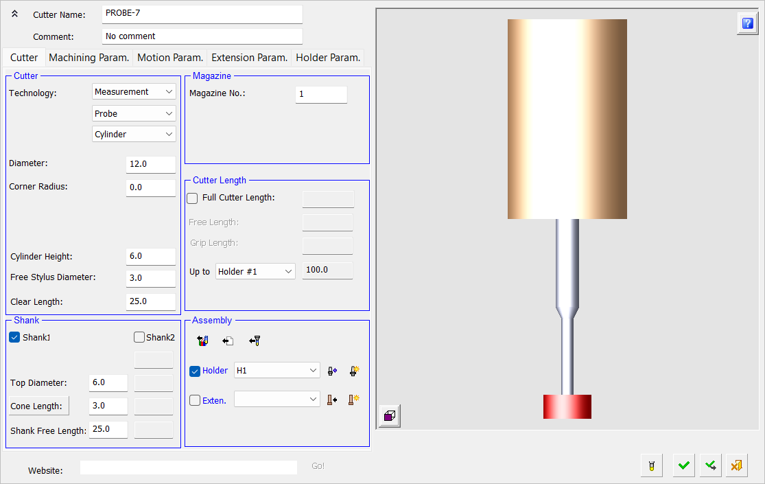
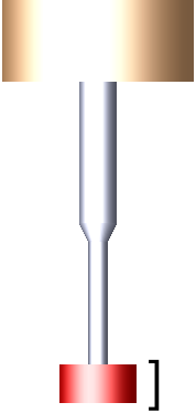
Cutter tab – Measure probe cylinder
Basic settings for creating a measurement probe
The following tabs and parameter definitions in the Cutters & Holders Dialog are relevant for measuring probes (only the differences for probes are mentioned below):
|
Cutter tab |
Diameter |
Diameter of the probe
|
||
|
Corner Radius |
For Measurement Probe Ball cutters, the Corner Radius is automatically calculated as half the tool diameter setting. For Measurement Probe Cylinder cutters, the valid Corner Radius settings are: Minimum setting = 0.0
|
|||
|
Taper Angle |
The Taper Angle parameter is OFF and unavailable. |
|||
|
Cylinder Height |
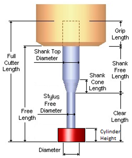
Height of the cylinder Minimum setting = 0.001
This setting is only displayed when the Cylinder option is selected in the Technology setting.
|
|||
|
Free Stylus Diameter |
A cylinder is added between the ball and the cone part of the shank. Its diameter is named Free Stylus Diameter and must be greater than 0 and less or equal to the tool diameter. Notes:
|
|||
|
Clear Length |
The Clear Length must be greater than the tool diameter.
|
|||
|
Shank |
The Shank checkboxes are available for use. The Shank Top Diameter is greater than or equal to the Shank Bottom Diameter.
|
|||
|
Machining Parameter tab |
Feed |
Only the Feed and Gouge Length parameters are available. |
||
|
Gouge Length |
||||
|
Motion Parameter tab |
Misc. Parameters |
Only the Misc. Parameters are available. |
If an In-Process Measurement procedure is created and no Measurement tool exists in the file, a generic probe will be created (similar to the "No Name" tool) with the following parameter settings:
- Cutter Name = "No Name Probe"
- Diameter = 6
- Corner Radius = 3
- Clear Length = 20
- Shank Top Diameter = 8
- Shank Bottom Diameter = 4
- Shank Cone Length = 4
- Shank Free Length = 50