|
|
Turning Tool Insert Types 

Access: Open this function from one of the following locations:
In the Turning Cutters dialog:
-
Select the New Cutter icon
 .
. -
Select the Edit Selected Cutter icon
 .
. -
Double-click a cutter row to edit the selected cutter.
In the Turning Cutter Definition dialog, select a turning tool insert from the dropdown list of available inserts.
Example dialogExample dialog
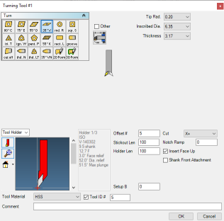
Tool information can be edited at any time by clicking on tool tiles and editing the information contained in the Tool dialog.
|
|
To change the icon size, right-click in an open area in or adjacent to this list and select the required size option.
|
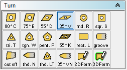
The following turning tool inserts are available to use with the tool holder. The insert parameters change according to the selected insert.
|
80° Diamond |
75° Diamond |
55° Diamond |
35° Diamond |
Round |
Square |
|
|
|
|
|
|
|
|
Triangle |
Trigon |
Pentagon |
55° Parallelogram |
Rectangle |
Grooving |
|
|
|
|
|
|
|
|
Cut Off |
Groove Style |
Lay Down Style |
35° Profiling |
2D Form |
3D Form |
|
|
|
|
|
|
|


Form Tool (2D or 3D)
The system supports custom form tools for Lathe parts. Unlike Mill parts, Lathe form tools must be a closed shape. Be sure to create the shape with the part origin in mind. The origin is used as the touch-off point for the tool. All posted output with this tool is relative to this point. Avoid concave shapes in your tool geometry if possible, unless that shape is actually used in the material removal.
A form tool does not have a tip radius, and so tool edge path is unavailable for form tools. The touch-off point is shown as a red cross in the tool diagram. If the toolpath generated from a form tool is undesirable, avoid drawing form tool geometry that is irrelevant to the actual cutting, such as the tool holder or areas of the insert that will not actually be used.
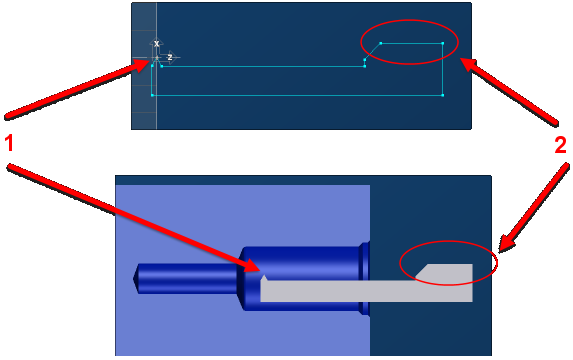
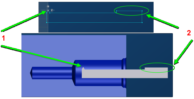
The illustrations below provide examples of correct and incorrect form tool geometry with its effect on toolpath. In the first example, form tool geometry extends past the touch-off point, resulting in a collision. In the second, form tool geometry is no higher than the touch-off point.
|
|
Bad results |
|
|
Good results |
|