Cutters and Holders Parameters  : Holder Parameters
![]()
![]()
Access: Open this function from one of the following locations:
The Cutters and Holders dialog (or the minimized version - the Select Only Mode):
-
When not editing or creating a procedure, select NC-Process > Cutters > Cutters from the menu bar or select Cutters
in the NC Guide Toolbar. -
While editing or creating a procedure, use one of the following methods (in both methods, the Select Only Mode is displayed):
-
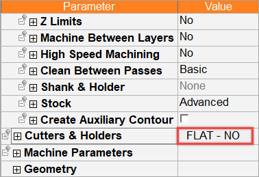
In the Advanced Mode, click on the cutter name in the Procedure Parameter Table.
-
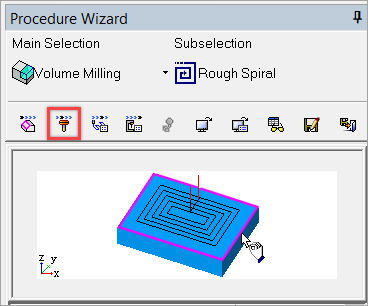
In the Wizard Mode, select the cutter button.
-
-
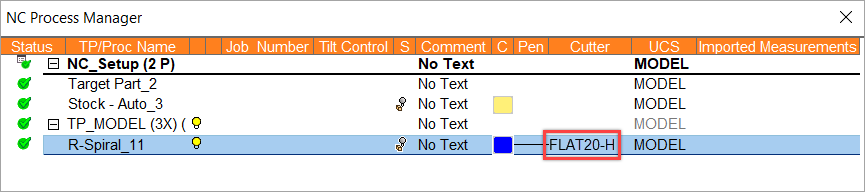
In the Process Manager, click on the cutter name in the procedure row (in this case, the Select Only Mode is displayed).
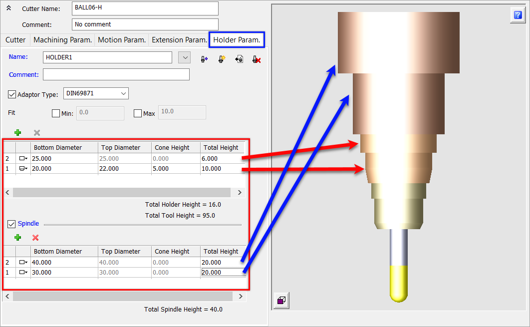
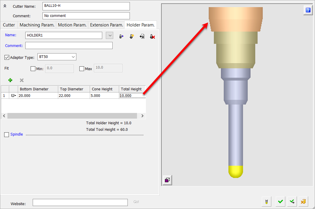
This topic explains how to define a Holder and Spindle for a cutter—Multiple Holders and Spindles can be defined.
In the image below, parameter fields in the red highlighted area will accept expressions such as 7/8, 5/25.4. Relations to other parameters (such as tldi/2) cannot be defined.
|
To display additional parameters, click the relevant tab in the dialog image below. |
An example cutter with a holder and multiple spindles. |
|
|
|
Notes:
-
The Total Cutter + Holder Height value is displayed.
-
If multiple Holders are defined, the Total Holder Height value is updated accordingly.
-
If multiple Spindles are defined, the Total Spindle Height value is updated accordingly.
On this page
- Adapter Type
- Fit Diameter
- Gouging
- Defining the Holder Parameters
- Set the Holder Parameters
- Defining a Spindle
- Holder Parameters tab Operation buttons
Adapter Type
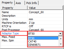
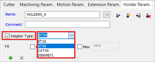
The Adaptor Type can be selected from a dropdown list. This parameter can be set in the NC Setup, Machine Definition, and also in the Holder Parameters tab of the Cutters & Holders dialog. This list of adaptors is the same for both locations and is saved in the following folder:
...\ProgramData\Cimatron\Cimatron\2026.0\Data\Nc\Machines-Adaptors.CSV
A warning is issued if the adaptor type of a holder is not identical to the adaptor type of a machine defined in the NC-Setup. The adaptor settings are compared and a warning is issued (if required) when the following occurs:
-
The holder specifies an adaptor.
-
The NC-Setup defines a Machine.
-
The Machine defines an adaptor.
-
The Adaptor type of the holder is different than the adaptor type of the machine.
If a warning message is displayed, you can either ignore and continue or cancel the selection of the holder. In the latter case, either modify the adaptor for the selected holder or select another holder with a suitable adaptor. When selecting a holder from the Holder Library, you can filter the holders by their adaptor type.
|
Adaptor Type Setting in |
Adaptor Type Setting in Cutters and Holder Dialog |
|
|
|
Fit Diameter
The minimum and maximum cutter or extension (if it is defined) diameter that can be mounted on the selected holder. This parameter appears in the Extension Parameters and Holder Parameters tabs.
When the checkboxes are checked, the top diameter of the cutter/extension is compared with the Min./Max. ranges entered when the Apply ![]() button is pressed. Error messages are displayed if the cutter/extension diameter is outside the selected range.
button is pressed. Error messages are displayed if the cutter/extension diameter is outside the selected range.
Gouging
In milling operations, the cutter holder may sometimes gouge the material. To avoid gouging, one or more holders may be defined for each cutter. If gouging is detected with the current holder, a different holder can be used instead.
Defining the Holder Parameters
Select the Holder checkbox in the Cutter tab of the Cutters and Holders dialog.
Note: When defining or editing a cutter, if the Holder checkbox is not selected (in the Cutter Parameters tab), the Holder tab is empty and the holder is not displayed in the Cutter Preview Pane.
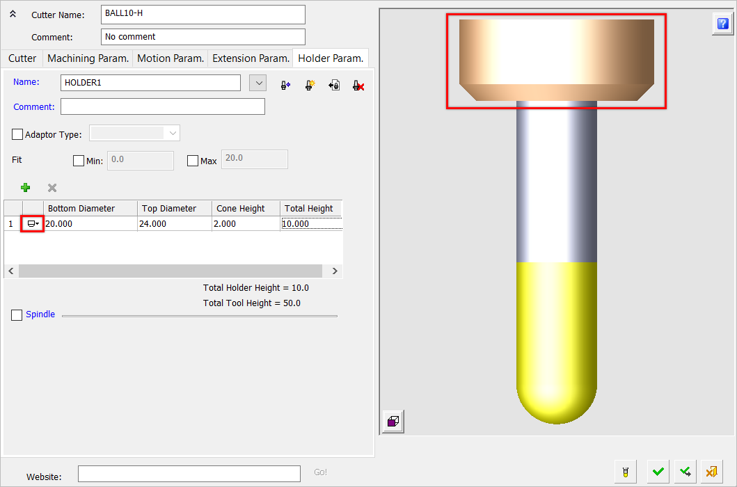
Open the Holder Paramaters tab. As shown in the other tabs, if a holder has been defined for this cutter (Holder checkbox in the Cutter Parameters tab), then the holder is displayed in the Cutter Preview Pane.
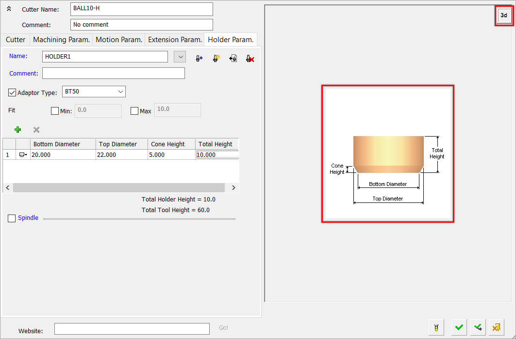
In this tab, the  /
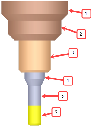
/  toggle button is displayed at the top right corner of the image and toggles between the Cutter Preview Pane and an image of the holder as shown below.
Define the appropriate parameters in this tab. Use this tab to perform the following steps.
-
Set the holder parameters, define a spindle and set its parameters- For the Holder(s) and Spindle the following parameters can be defined: Bottom Diameter, Top Diameter, Cone Height, and Total Height. Parameters for each holder or spindle are made active according to the shape. The preview of the holder and spindle dynamically changes according to parameter changes.
-
Use the operation buttons to import holders from the Holder Library, create new holders, and/or delete unused holders.
Click Apply ![]() to accept the holder definitions.
to accept the holder definitions.
To return to the cutter definition dialog, open the Cutter tab or if you are finished defining cutters, click OK ![]() .
.
Set the Holder Parameters
The following parameters can be defined for each holder
-
Bottom Diameter
-
Top Diameter
-
Cone Height
-
Total Height
You can add or delete holders for this cutter.
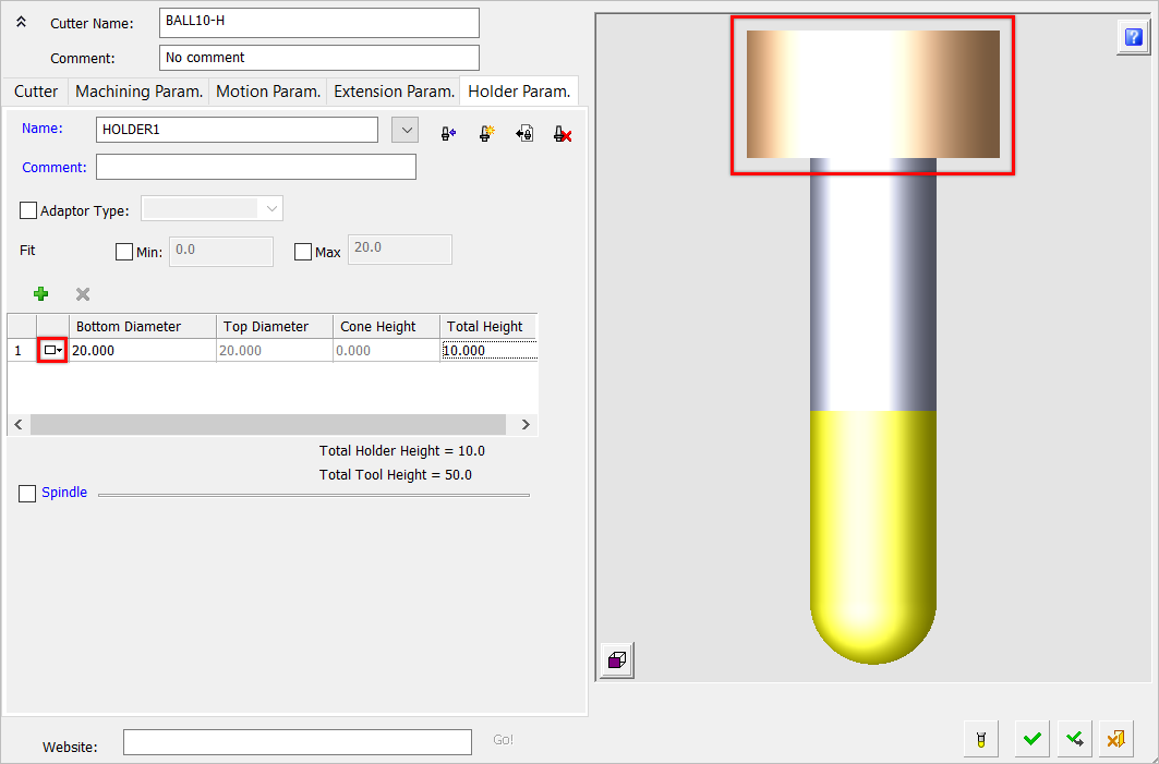
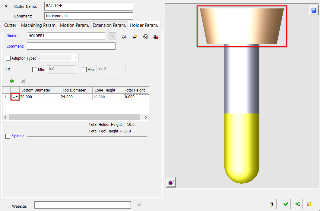
Define the shape of the holder by clicking on the icon to the left of the table and toggling between the following holder shapes (Cylindrical / Conic / Cylindrical and Conic) ![]() .
.
The Holder parameters that are only made available for configuration depend on the shape selected. The display of the holder dynamically changes according to parameter changes.
ExamplesExamples
|
Holder: Cylindrical |
|
|
|
Holder: Conic |
|
|
|
Holder: Cylindrical and Conic |
|
|
Adding a holder
- To add another holder, click the Add
 button.
 - In the new Holder row, set the holder parameters as required.
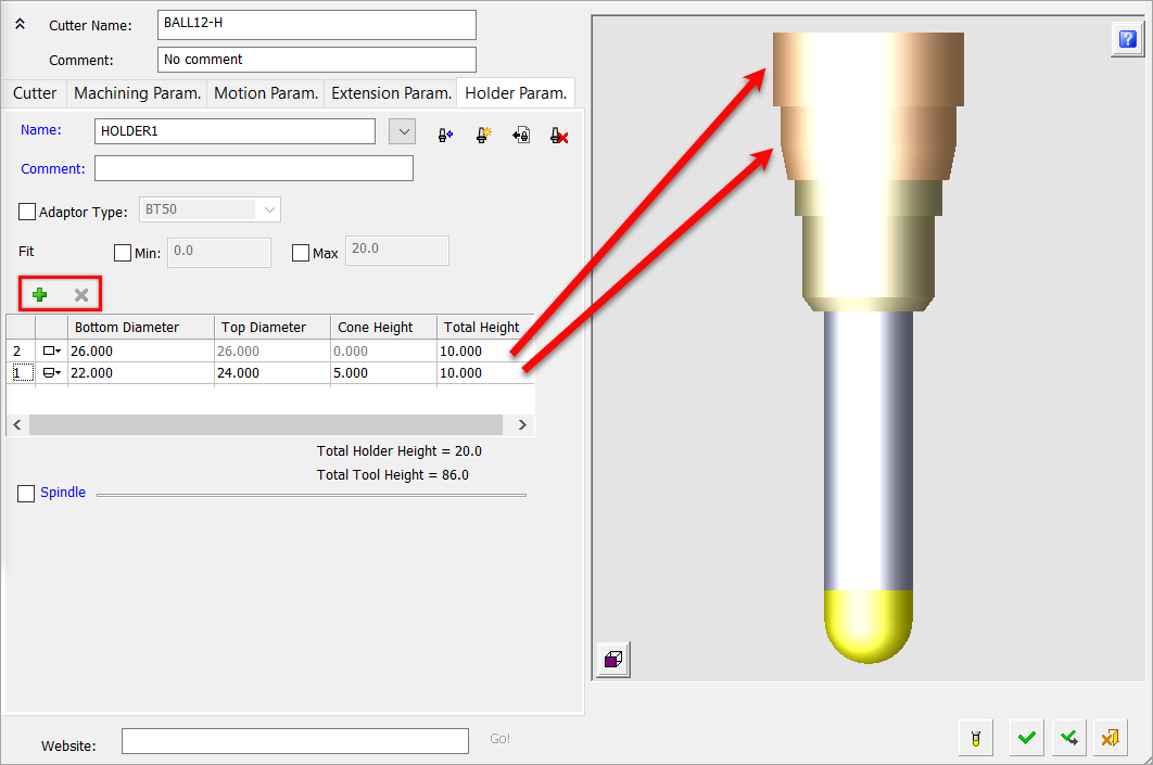
Note: If the shape of the added holder is not permitted, the appropriate parameters are displayed in RED and the cutter image changes to the holder image.
Deleting a Holder
- To delete a holder, select the appropriate holder number
- Click the Delete
 button. The selected holder is deleted and the cutter image in the dialog is updated.
Defining a Spindle
Define a spindle, if required, and set its parameters. By default, the spindle checkbox is not selected.
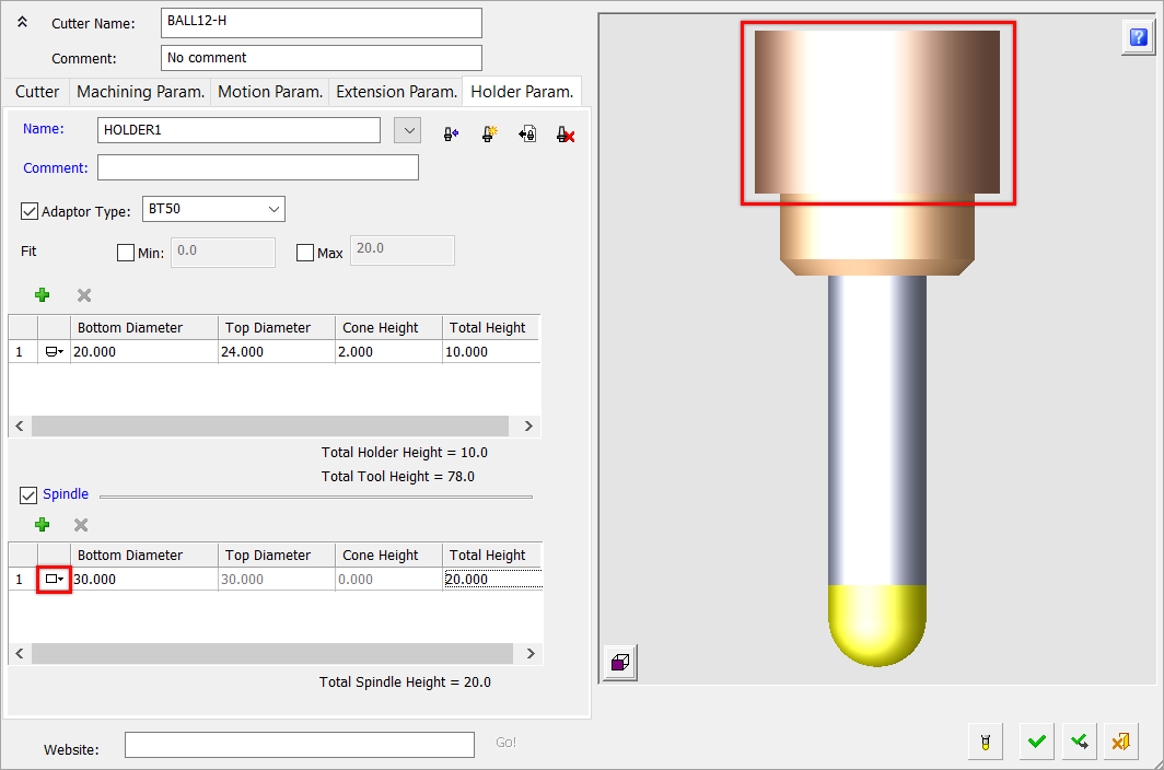
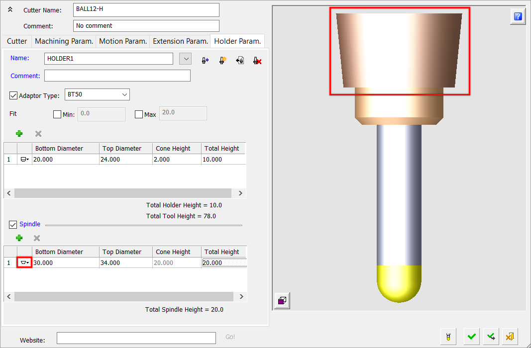
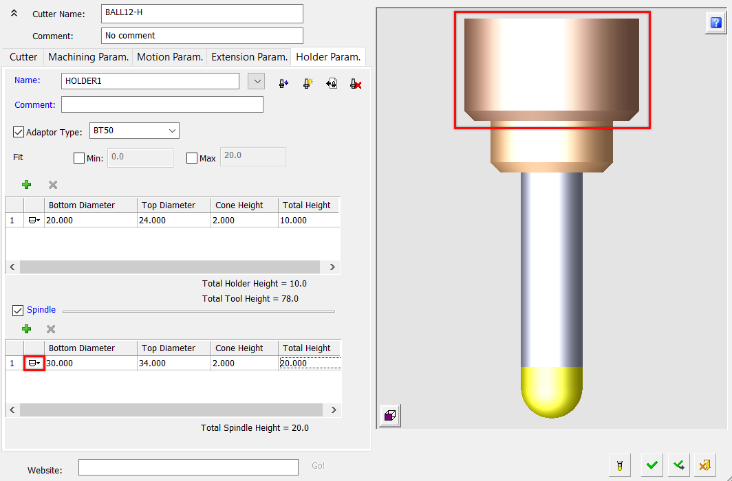
Select the checkbox to display the spindle parameters: Bottom Diameter, Top Diameter, Cone Height, and Total Height.
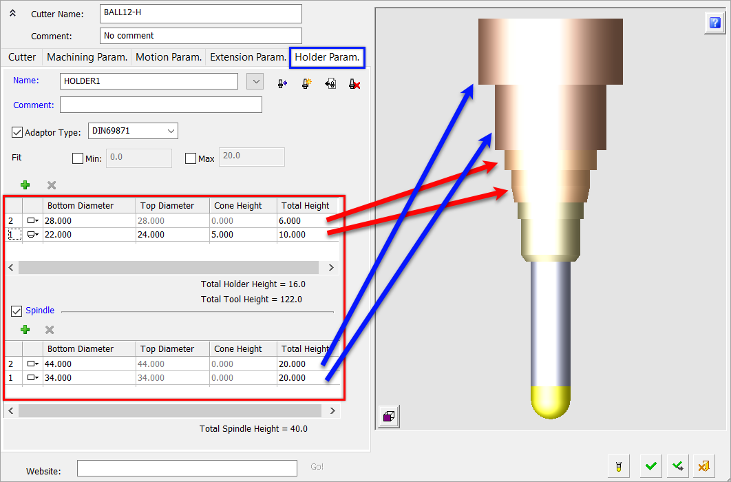
Define the shape of the spindle by clicking on the icon to the left of the table and toggling between the following spindle shapes (Cylindrical / Conic / Cylindrical and Conic) ![]() .
.
Spindle parameters are enabled/disabled according to the shape selected. The display of the spindle dynamically changes according to parameter changes, similar to the display of the holder.
ExamplesExamples
|
Spindle: Cylindrical |
|
|
|
Spindle: Conic |
|
|
|
Spindle: Cylindrical and Conic |
|
|
Operation buttons
The following operation buttons are available in this tab.
|
|
Load a Holder From the Holder Library: The Holder Library dialog is displayed; select a holder as required. The selected holder is loaded into the cutter table of the currently active NC file and its parameters are displayed in the Holder Parameters tab. The parameters of the holder can subsequently be edited without affecting the Holder Library from which they were imported. |
|
|
Create a New Holder: This option enables you to create a new holder for cutter. Define the parameters of the new holder as appropriate. The new holder is added to the cutter table of the currently active NC file and its parameters are displayed in the Holder Parameters tab. Notes:
|
|
|
Delete Unused Holders: This option enables you to delete holders that are unused in the currently active NC file. If there are no unused holders in the currently active NC file, an appropriate message is displayed. If there are unused holders in the currently active NC file, the Delete Unused Holders dialog is displayed listing all the holders in the currently active NC file. All unused holder names are automatically selected for deletion; scroll down and unselect holders if required. All used holder names are disabled (grayed out) and cannot be deleted.
Press OK |