Simulator 
![]()
![]()
Access: Select one of the following methods to access the Simulator:
-
Select NC-Process > Simulation > Machining Simulation from the menu bar.
-
Select
 from the NC Guide.
 -
Right-click on an item in the Process Manager and select Simulation - Machining from the popup menu.
-
Select the Simulation button in the Job Manager.
The Machining Simulation dialog is displayed. Set the required parameters and press OK ![]() to display the Simulator.
to display the Simulator.
The Machining Simulation tools offer a combined environment for machining simulation that includes the following capabilities: material removal simulation, machine simulation, and verifier. These tools enable you to simulate and verify your NC toolpaths and procedures before implementing them on the shop floor.
Checking the actual C-Code against the machine kinematics and CNC control system of a specific machine can eliminate both the need for on-machine CNC program try outs and the possibility of costly collisions.
Although Machining Simulation is performed on a separate screen, it is easy to use in tandem with the NC environment. You can quickly switch back and forth between these two windows by using the icons in the lower right of the screen. For example, in the event of a simulation issue, this allows for the exact transfer of Z layer or block number information between the two for a thorough investigation of the problem.
The following buttons are displayed at the lower right of the screen:
|
|
|
Switch To CAM Mode (NC programming). |
|
|
Machining Simulation. |
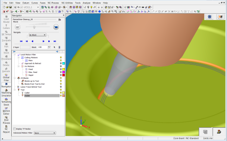
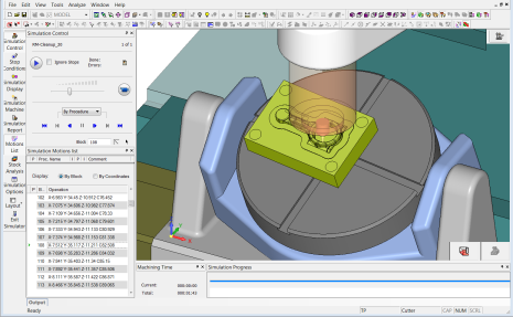
Examples of the programming and machining simulation environments are shown below.
|
The programming environment |
The machining simulation environment |
|
|
|
The embedded machine simulator includes:
-
Machine kinematics and axis limits
-
Manual axis control
-
Display of the G-code window with the current block marked.
The simulator also offers full control over the display of:
-
Machine components and fixtures
-
Part, initial stock and current stock
-
Tool, holder and toolpath.
In the machine simulator environment, material removal simulation and verification are also available.
A detailed example of the machine simulation environment is displayed below.
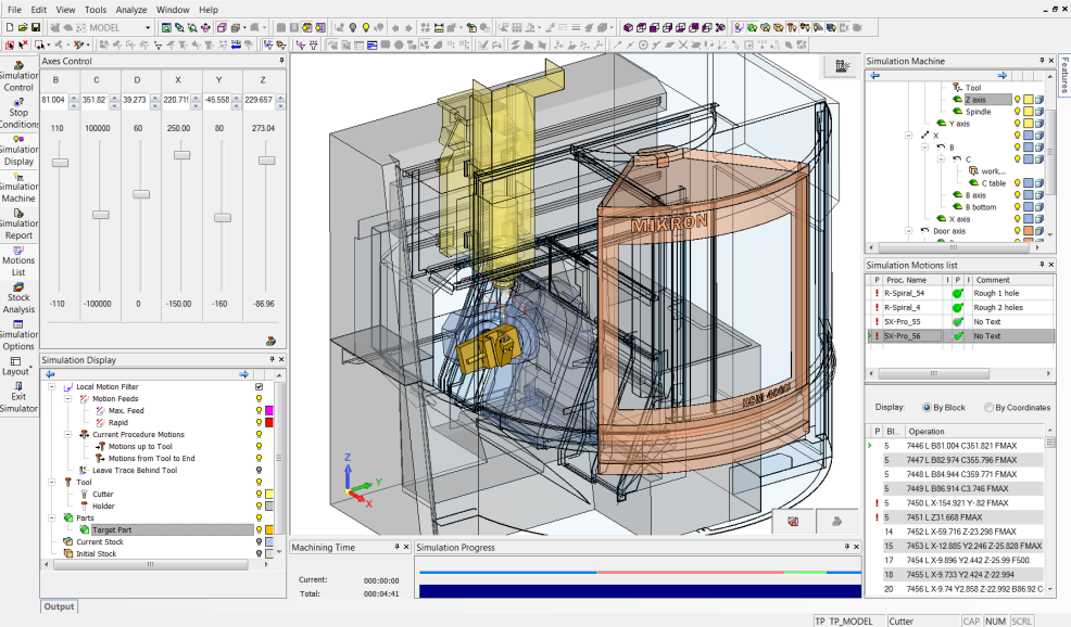
The above image shows:
- Left – Manual axis control and component display
- Right – Machine component display, procedure list, and "G-code"
- Bottom – Machining time and progress bar
The simulator provides the following:
The simulation (Machine Simulation and Material Removal Simulation) is highly accurate and reliable, as is the gouge and collision detection and the color-coded deviation distance map.
Visual representation is of the highest quality, whether it is of the entire stock or a zoomed-in view.
As an embedded tool there is a unified user interface and seamless data flow from Cimatron to the simulator. It can be viewed either as a window in the same session or as a standalone window. Data from the simulator is fed back into Cimatron; the toolpath motions are tagged where there is a gouge or collision and you are then able to analyze these motions in the Cimatron Navigator.
You have the option of selecting one of the following simulation modes from the Machining Simulation dialog:
|
The Accurate and Quick modes are used for the following (depending on the options selected):
The Accurate mode is the most accurate simulation, taking the required amount of time to achieve the high quality results. The Quick mode is a faster simulation with looser tolerances. Quick is the default mode. |
|
|
The Super Turbo mode is used for:
The Super Turbo mode is the fastest simulation with the loosest tolerances; it provides you with an indication of whether there are likely to be any major problems in the material removal process. Note that this mode is only available for 3-axis machining and only for material removal simulation; it cannot be used for machine simulation. |