Add Wedge  : Global Wedge
![]()
![]()

Access: Open this function from one of the following locations:
-
Select Mold Design > Insert > Add Wedge from the menu bar.
-
Select Die Design > Insert Tools > Add Wedge from the menu bar.
-
Select Insert > Add Wedge from the Mold Design Guide or Die Tool Design Guide (DieDesign).
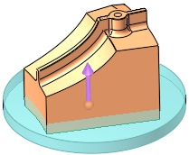
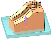
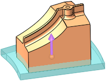
Add a wedge to a solid object to lock it in position. A cutting object can also be selected.
The Add Wedge function enables the creation of a wedge on a selected face of an object. You can create different wedge types, either applying custom shapes (box, circle, enclosing polygon, etc.) or manually defining a wedge’s placement along individual edges. In addition, a cutting object with optimized geometry can be defined for the wedge. See Insert Tools for an introduction to inserts.
For the other steps of this function, see Add Wedge: Options and Results.
Required Step 2 
-
Set the global wedge parameters.
Global
This is a toggle option, Global / Local, which enables you to define where the wedge is to be added:
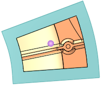
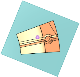
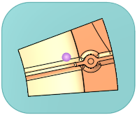
Global
Add the wedge globally around the face selected in step 1.
Example:Example:This is the default option. See Global Parameters for descriptions of this option.
Local
Add the wedge locally to an edge of the face selected in step 1.
Example:Example: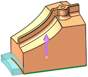
See Local Wedge for parameter descriptions of this option.
Global Parameters
Add the wedge globally around the face selected in step 1.
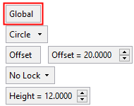
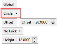
Circle
Define the shape of the global wedge. This is a dropdown list of the following options:
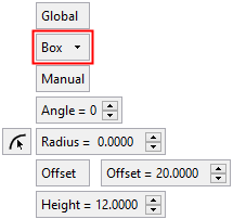
Box
Add a box shaped wedge around the selected face. The following parameters are displayed:
Example:Example:Box parameters and preview:
Top view:
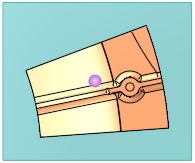
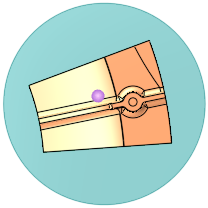
Circle
Add a circle shaped wedge around the selected face. The following parameters are displayed:
Example:Example:Circle parameters and preview:
Top view:
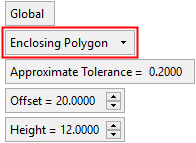
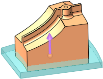
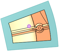
Enclosing Polygon
Add an enclosing polygon shaped wedge around the selected face. The following parameters are displayed:
Example:Example:Enclosing Polygon parameters and preview:
Top view:
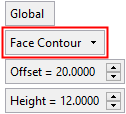
Face Contour
Add a face contour shaped wedge around the selected face. This wedge option reflects the contours of the selected face. The following parameters are displayed:
Example:Example:Face Contour parameters and preview:
Top view:
Manual
This toggle option is only displayed if the Box method is selected and enables you to define the size and orientation of the bounding entity. The toggle options are Manual / Auto:
Manual
The Manual option gives you control over the shape/orientation of the bounding entity. When this option is used, the Angle and Radius parameters are available
Auto
The Auto option automatically finds the angle which creates the smallest bounding entity. When this option is used, the Angle and Radius parameters are grayed out and are not available.
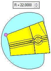
Angle
This parameter is only displayed if the Box method is selected and enables you to define the orientation of the wedge box.
Example:Example:Angle = 0°:
Angle = 22°:
Radius
This parameter is only displayed if the Box method is selected and enables you to define the radius of the wedge box corners. The Radius can either be set by entering the required value into the field or by clicking the
 button to take the information from existing geometry (by picking a cylindrical face or a point).
Example:Example:Radius = 0:
Radius = 15:
Approximate Tolerance
This parameter is only displayed if the Enclosing Polygon method is selected and enables you to define if the result is approximate to the specific tolerance.
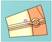
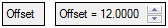
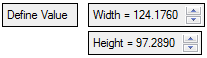
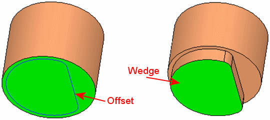
Offset
This parameter enables you to set the size of the wedge entity, either by defining an offset value or by setting the width, height or radius of the wedge entity, as follows (see the Offset notes below):
Example:Example:Offset = 12:
Offset = 20:
-
In the Box option - the Offset option can be toggled to Define Value, enabling you to set the Width and Height of the wedge box.
Example:Example:Offset
Define Value
-
In the Circle option - the Offset option can be toggled to Define Value, enabling you to set the Radius of the wedge circle.
Example:Example:Offset
Define Value

-
In the Enclosing Polygon and Face Contour options - only Offset is available.
Example:Example: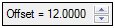
For all the wedge shape options, the Offset values can be positive, negative or zero, except for the Face Contour option, where 'zero' is not allowed.
Notes:
-
When using the Global option and the defined Offset values (or Define Values) are ≥ the minimum bounding box of the selected face, the results would be as follows:
Example:Example: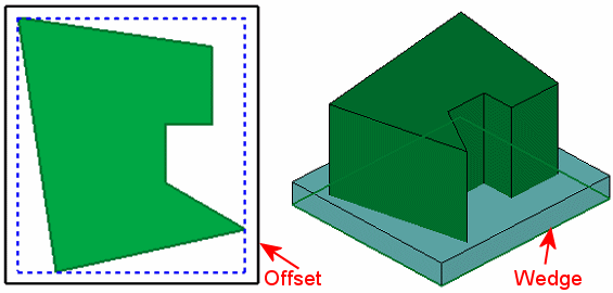
-
When using the Global option and the defined Offset values (or Define Values) are < the minimum bounding box of the selected face, the results would be as follows:
Example:Example: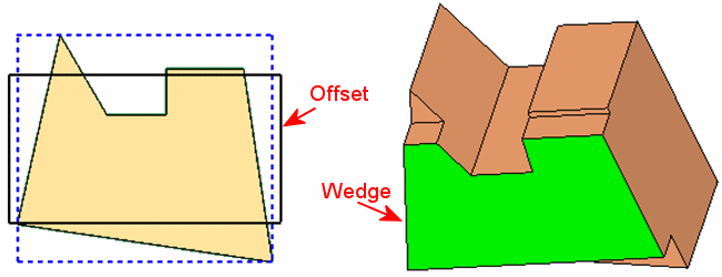
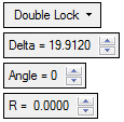
No Lock
Define whether the wedge has a lock and of which type, from the dropdown list of the following options:
Example:Example:None
Single Lock
Double Lock

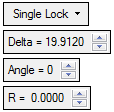
For the Single or Double Lock options, the following additional parameters are displayed:
Delta
Set the distance of the lock from the circle center.
Example:Example: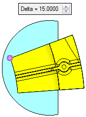
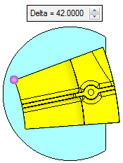
Default: Circle Diameter x 0.25
Valid values: > 0 and < Dia/2 (if the entered value is ≥ Dia/2, the parameter is displayed in red and the lock operation is not carried out.Angle
Set the angle to define the orientation of wedge.
Example:Example: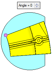
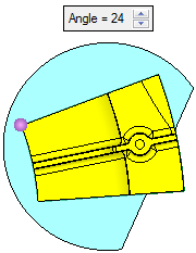
Valid values: 0 to 360 degrees.
R
Set the radius of the wedge corners.
Example:Example: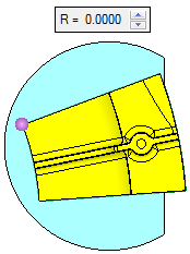
Valid values: ≥ 0.
Height
Set the height of the wedge. This parameter appears for all Global and Local options; the example below is for a Local wedge.
Example:Example: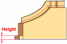
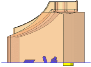
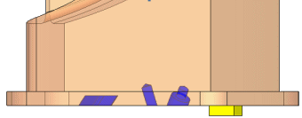
If the selected face (to which the wedge is to be added) contains internal loops (holes or protrusions), the added wedge takes these into account.
Example:Example:In this example, the holes are colored blue and the protrusion is yellow:
The added wedge take these entities into account:
-