Add Wedge  : Options and Results


Access: Open this function from one of the following locations:
-
Select Mold Design > Insert > Add Wedge from the menu bar.
-
Select Die Design > Insert Tools > Add Wedge from the menu bar.
-
Select Insert > Add Wedge from the Mold Design Guide or Die Tool Design Guide (DieDesign).
Add a wedge to a solid object to lock it in position. A cutting object can also be selected.
Add Wedge is a function used
for automating mold insert design. The wedge serves to hold it under the
cavity block without requiring a fastener. This function has many options
that help you create either a full or partial wedge based on any possible
insert shape, either applying custom shapes (box, circle, enclosing polygon,
etc.) or manually defining a wedge's placement along individual edges.
It also features a built-in cutting object that allows you to create a
matching pocket in the mold cavity.
See Insert
Tools for an introduction to inserts.
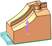
Required Step 1 
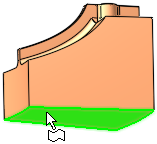
- Pick the 2D planar face to which the wedge is to be added (the face should not contain open edges):
- Click OKOK
 when complete to continue.
Required Step 2 
-
Set the parameters. The parameters are displayed, together with a preview of the wedge:
Global Wedge parameters:
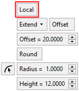
Local Wedge parameters:
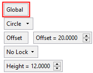
Global
This is a toggle option, Global / Local, which enables you to define where the wedge is to be added:
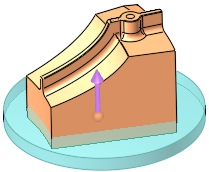
Global
Add the wedge globally around the face selected in step 1.
Example:Example: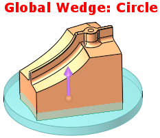
This is the default option. See Global Wedge for parameter descriptions of this option.
Local
Add the wedge locally to an edge of the face selected in step 1.
Example:Example: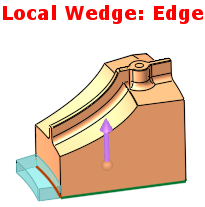
See Local Wedge for parameter descriptions of this option.
Optional Step 1
-
Set the cutting object parameters for the wedge. The following parameters are displayed:
Cutting Object
This is a toggle option, Cutting Object / None, which enables you to define a cutting object.
If Cutting Object is selected, the parameters below are displayed.
If None is selected, no parameters are displayed and no cutting object is defined.Cutting Object parameters
Top Clearance
The top clearance for the cutting object. See the image in the Bottom Clearance parameter description.
Default: 0mm/inch.Bottom Clearance
The bottom clearance for the cutting object.
Example:Example:
Default: 5mm (0.2 inch).
Global Wedge Offset/
Local Wedge OffsetThe Global Wedge Offset parameter is displayed only if the Global option was selected in step 2. This parameter is located as shown in the image below, on the side of the face which is not part of the local offset.
The Local Wedge Offset parameter is displayed only if the Local option was selected in step 2. This parameter is located as shown in the image below, on the side of the face which is part of the local offset.
Example:Example:
Additional examples showing the Global and Local Wedge Offsets:
Note: This parameter is not displayed if a Circular wedge with a Single or Double Lock is selected in step 2. Instead of this parameter, the following parameters are displayed, Circular Face Offset, Locking Face Offset and Radius - see below.
If a Circular wedge with a Single or Double Lock is selected in step 2, the Circular Face Offset, Locking Face Offset and Radius parameters are displayed instead of the Global Wedge Offset/Local Wedge Offset parameter:
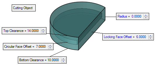
Circular Face Offset
Set the offset for the circular face of the cutting object.
Default: 0 mm/inch.Locking Face Offset
Set the offset for the locking face of the cutting object.
Default: 0 mm/inch.Radius
Set the radius of the cutting object.
Default: 0 mm/inch.If the added radius intersects the original wedge body (including the R value if defined), this parameter is displayed in red.
Example:Example: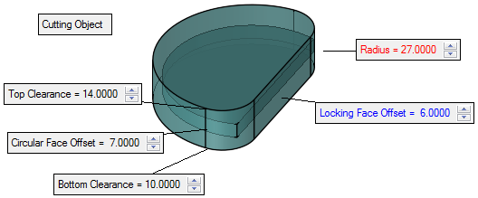
-
Click OKOK
 or ApplyApply
 in the Feature Guide to complete the function.
When completed, the Add Wedge feature will appear in the Feature Tree as follows: