Addendum : Options and Results
![]()
![]()

Access: Open this function from one of the following locations:
-
Select Die Design > Geometry Manipulation > Addendum from the menu bar.
-
Select Geometry Manipulation > Addendum from the following Die Design Guide: Die Process Design Guide (Forming).
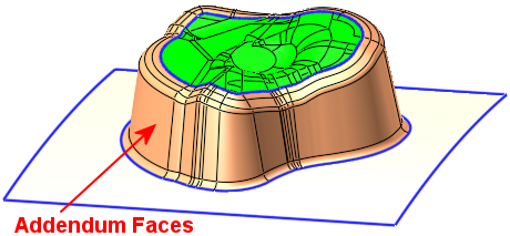
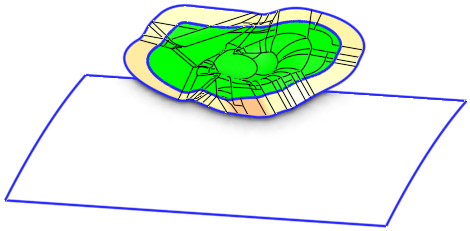
Create addendum faces between the blank faces and the binder. Addendum faces are those that bridge between the part (blank) faces and the binder faces. A predefined list of cross section shapes are available for the definition of the addendum faces.
Addendum faces are mostly required in Transfer and Regular Die design, where large-medium parts are transferred between multiple presses to complete them, such as shells, tube applications, frames and structural components.
|
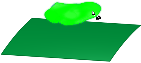
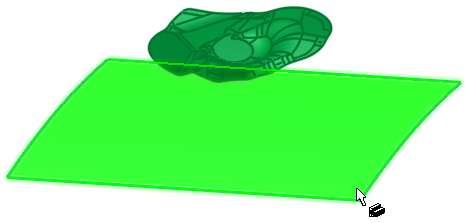
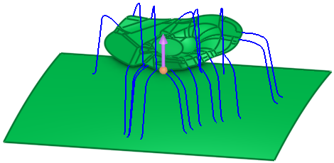
The part and binder objects |
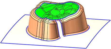
The resultant smooth addendum faces |
|
|
|

Required Step 1 
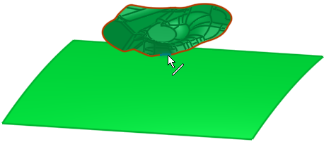
- Click on a part object to pick it. All the faces adjacent to the outer boundary of the selected object must be smooth.
Required Step 2
- Click an open smooth binder object or a plane to pick it.
Required Step 3 
-
A direction arrow is displayed (for the direction of the created addendum faces), with the default direction being the +Z of the active UCS.
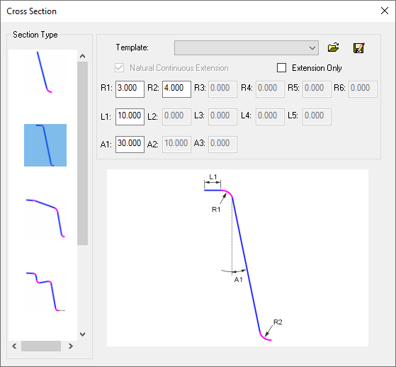
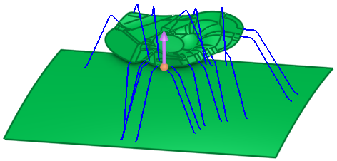
Define the addendum type and set the parameters. The Cross Section dialog is automatically displayed showing a list of predefined cross section shapes for the definition of the addendum faces. A preview of the results of the parameter settings is displayed in the graphics window.
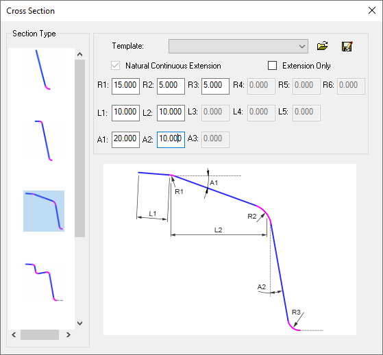
Preview result of the selected parameter settings in the Cross Section dialog
Parameters
Show Dialog
Show or hide the Cross Section dialog.
Cross Section Dialog
Section Type
Select the type of section that defines the section shape of the addendum faces. Each section type produces different shaped addendum faces. The selected section shapes are displayed in the graphics window.
ExampleExample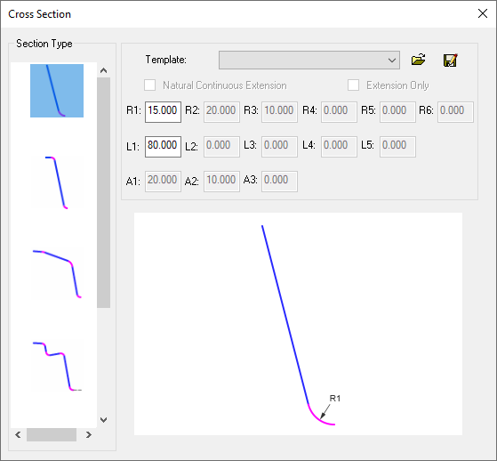
Preview result of the selected parameter settings in the Cross Section dialog
Preview result of the selected parameter settings in the Cross Section dialog
Template
Displays the loaded template of saved parameter settings.
Natural Continuous Extension
When this option is ON, create extensions continuous with the faces of the object selected in step 1, and in accordance to the Section Type selected in the dialog.
For new features, the default is ON and dimmed.
When editing features created prior to version 16, this option is OFF ; you can switch it ON to get a new extension.
Extension Only
When this option is ON, only the extension faces will be created; all the parameters in the dialog are dimmed, except for L1. This is reflected in the preview.
ExampleExample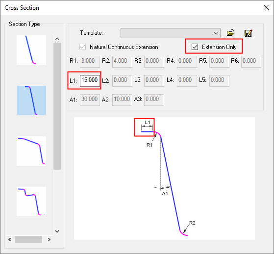
Extension Only is selected - only the L1 parameter is available
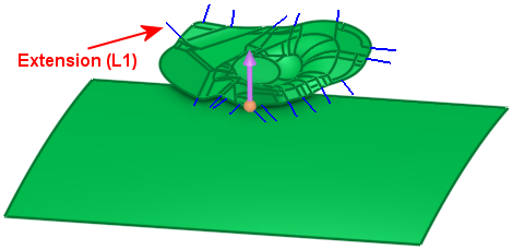
Preview result of the selected parameter settings in the Cross Section dialog
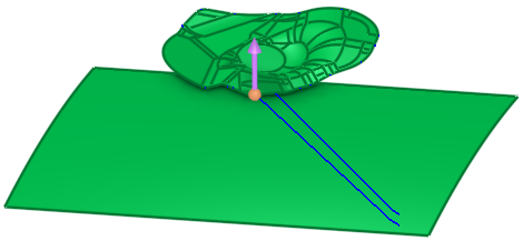
Result of an Extension Only operation
This parameter is only available if the Natural Continuous Extension parameter is ON
.Parameters
Edit the parameters available for each selected Section Type. Depending on the Section Type selected, some parameters may not be available.
Each section type displays its own user-defined parameters and also an image of the section shape, showing the effect of each parameter on a specific segment of the section.
The parameters are displayed in rows marked R, L and A, with each parameter numbered:
R<n>
The Radius values controlling the section shape.
L<n>
The Length values controlling the section shape.
A<n>
The Angle values controlling the section shape.
Dialog Buttons
The following buttons are in the dialog

Open: Browse to and select/open the required file.
Open the template file of containing the saved parameter settings.
 Save As: Save the current settings in a different file.
The current parameter settings are saved in an addendum template file.
Addendum templates are stored in ADT files in the following folder:
...\ProgramData\Cimatron\Cimatron\2026.0\Data\Die\Addendum
Optional Step 1 
-
Click to deselect boundary edges of the part where addendum faces are not to be created.
To create addendum faces on the deselected edges, edit the function and click the unpicked boundary edges.A boundary edge of the part is selected:
An addendum face is not created on the selected edge:
- Click OKOK
 or ApplyApply
 in the Feature Guide to complete the function.
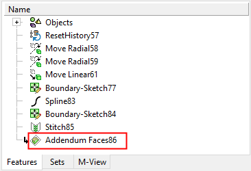
When completed, the Addendum Faces feature will appear in the Feature Tree.