Dynamic Constraints: Alignment with Existing Entities
Notes:
-
The constraints that appear on the screen depend on which entities are currently in the display area. For example, you will not see parallel constraint to a line that is not in the display.
-
If you want to create alignments with entities that are not in the current sketch, you must add the entities to the sketch as reference entities.
-
You can also add constraints after entities are created. See Adding Constraints.
-
You can control which constraint lines appear by the Constraint Filter.
Purple Constraint Lines
On a curve, co-linear
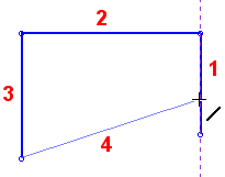
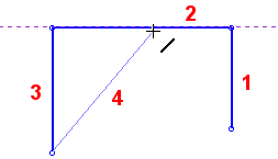
When an endpoint lies on or is co-linear with an existing line, a dashed purple constraint line is displayed.
|
The endpoint of line 4 lies on line 1. |
The endpoint of line 4 is co-linear with line 2. |
|
|
|
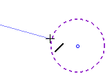
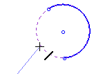
When an endpoint lies on a circle, arc, or the extension of an arc, the circle / arc is displayed in dashed purple.
|
|
|
Cyan Constraint Lines
Parallel and Tangent
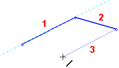
When a new line is parallel to an existing line, a dashed cyan constraint line appears.
|
Line 3 is parallel to line 1. |
|
|
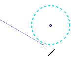
When a new line is tangental to a circle, arc, or the extension of an arc, the circle/arc is displayed in dashed cyan.
|
The line is tangent to the circle. |
|
|
Dashed Pink Constraint Lines
Normal
When an endpoint is normal to an existing line, a dashed pink constraint line appears.
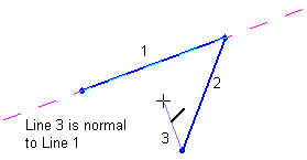
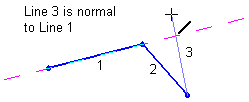
Note: Any new entity positioned using Dynamic Constraint Lines will be constrained to either the existing entity or the X-Y axis. When the new entity is positioned relative to an existing entity, a mutual constraint relationship is created with the existing entity. You can break an entity's constraints to make it independent of all other entities and the X-Y axis.
