Contour Manager (NC) > By NC Pockets Contour Selection
![]()
![]()
Access: Open this function from the following location:
Boundary/Contour selection mode:
Either press the button in the Work
Mode Dialog (if you are in Wizard
Mode), or display the Geometry
parameters in the parameter
tables.
button in the Work
Mode Dialog (if you are in Wizard
Mode), or display the Geometry
parameters in the parameter
tables.
The Geometry Table is displayed:
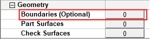
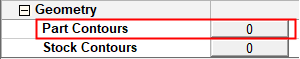
Depending on the current operation, the Boundaries or Contours option is displayed. Press the adjacent button to display the Contour Manager; you are ready to start selecting contours.
See Selecting / Unselecting Geometry.
See the cursor symbols in Cimatron when picking geometry.
Create NC contours from previously recognized NC Pockets.
The Pocket Selection dialog is displayed. This is similar to the Pocket Manager dialog, however, it is used for selection only and not for recognizing new pockets. The geometry selected (for example, the pocket's volume, surfaces or contours) depends on the active procedure. As when the Pocket Manager is active, the pre-recognized pockets are highlighted in the graphics window.
See Pocket Output Geometry for Downstreaming, below.
|
|
This dialog is similar to that of the Pocket Manager and the Contour Manager dialog, with differences resulting from the functionality.
|
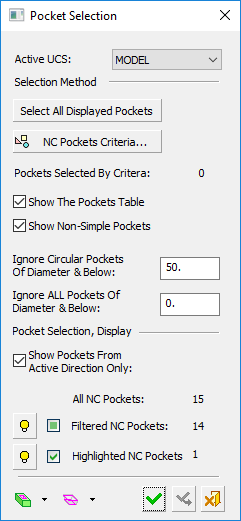
The lower part of the Pocket Selection dialog, Pocket Selection, Display, enables you to hide/show and select pockets and provides you with the following information:
|
Only show pockets created on the active UCS direction. |
|
|
Filtered NC Pockets |
The number of filtered NC pockets (the number of lines in the Pocket Table, whether or not the table is displayed). |
|
Highlighted NC Pockets |
The number of NC pockets currently highlighted in the Pocket Table (i.e,where the rows are highlighted |
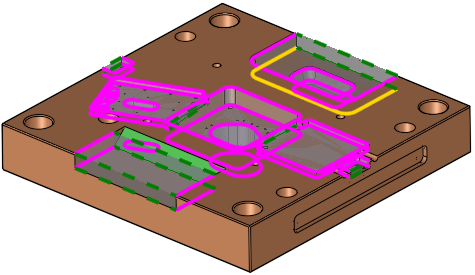
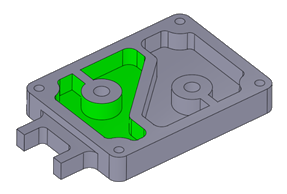
When a pocket is selected, its bottom contour is by default highlighted in yellow to signify that it has been selected for the contour selection operation. If required, you can pick the top contour of the pocket, instead.
|
|
|
In the Pocket Selection dialog, click the Show the Pocket Table checkbox to display the NC Pocket Table dialog. This is similar to the Pocket Table displayed from the Pocket Manager, but with an additional Selection column that when ON, signifies that this pocket's contour is selected for the contour selection operation.
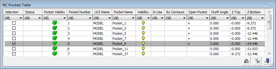
Pockets can be selected using any of the following methods (see the Pocket Manager for detailed information):
-
Pocket Selection dialog: Use the dialog selection controls - Select all Displayed Pockets and NC Pockets Criteria.
-
Graphics display: Select pockets by picking them.
-
Pocket Table: Select pockets by picking rows. Use the sorting capabilities of the Pocket Table, as required; for example, filter all pockets with the same draft angle.
Note: A pocket is only selected for the procedure operation if the checkbox in the Selection column is ON. If the checkbox is OFF, this means that the pocket has been selected for another purpose, such as Hide/Show.
Pocket Output Geometry for Downstreaming
|
Recognition of all pockets in a Plate is a preliminary step for automating the process of pocket machining. The recognized pockets can be used in downstream procedures and templates. The relevant geometry from the Pocket feature is automatically selected by the procedure. For example, the Volume Pocket procedure takes the pocket’s volume, the Finish procedures take the surfaces and the Profile procedures (Profile Closed Contour and Profile Open Contour) take the contours and Z values. |
The image shows that, for selected pocket(s), the surfaces associated with the pocket(s) are automatically selected.
|
The following pocket geometry output rules apply.
-
When using procedures, the output from a pocket may be:
-
Its volume.
-
Its surfaces.
-
Its contours and their numeric values (as boundaries).
-
-
When pockets are selected By NC Pockets from the Contour Manager, only contours with their numeric values (heights) are output from the pocket.
-
When pockets are selected by Pockets in the Geometry parameters table, the output depends on the procedure type:
-
Rough Spiral, Rough Parallel, Volume Pocket:
-
The surfaces of selected pockets are used as part surfaces (group one).
- The volumes of selected pockets are used as Stock.
-
The contours are not used.
-
Safe Milling and Stock work in a similar way to Volume Pocket.
-
Surfaces and Contours that are selected directly (by criteria or manually) are used.
-
-
Finish, Cleanup, Rest Milling and Pencil:
-
The surfaces of selected pockets are used as part surfaces (group one).
-
These surfaces (from pockets) create Automatic Boundaries with default settings.
-
The volumes of selected pockets are not used.
-
The contours are not used.
-
Safe Milling and Stock work normally.
-