Analysis (toolpath) Docking Pane
The toolpath analysis applies colorization schemes on the toolpath, which let's the users analyze it from the following features point of view:
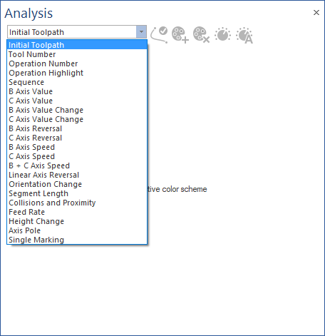
Initial Toolpath
The toolpath line and points are received already colorized and the positions already specified from the CAD/CAM system.
Machine Simulator only displays the toolpath. The CAD/CAM system have full control over the toolpath colors and positions.
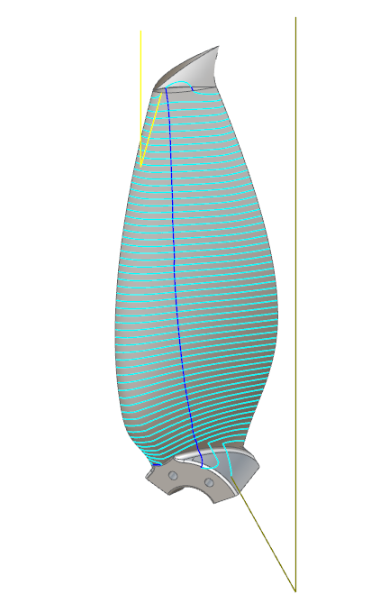
Tool Number
The toolpath will be colorized after the different tools being used.
Identifies the amount of different tools being used and the area in which a certain tool is machining.
-
Color: used to select a specific color.
-
Tool Number: represents the tool number given in the CAD/CAM system.
-
Tool description: represents a more detailed description of the tool.
-
Used for operation: specifies for which operation the tool is used.
-
Refresh: applies the last modifications made by the user.
-
Auto Adjust: resets the colors and number of them to default.
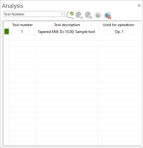
Operation Number
The toolpath will be colorized after the different operations being used.
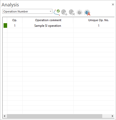
Identifies the quantity of different operations and the area a certain operation is performing a machining.
-
Color: used to select a specific color.
-
Op.: represents the operation number given in the CAD/CAM system.
-
Operation comment: represents a more detailed description of the operation.
-
Unique Op. No. : specifies unique operation number.
-
Refresh: applies the last modifications made by the user.
-
Auto Adjust: resets the colors and number of them to default.
Operation Highlight
The toolpath will be colorized depending on whether is from the current operation or from other operations.
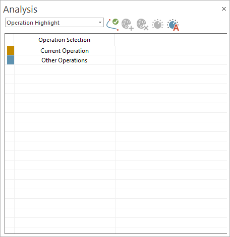
Identifies the toolpath for the current operation or if it is part of other operations, and the area in which the current operation is performing machining.
-
Color: used to select a specific color.
-
Operation Selection: represents the current operation and other operations given in the CAD/CAM system.
-
Refresh: applies the last modifications made by the user.
-
Auto Adjust: resets the colors and number of them to default.
Sequence
The toolpath will be colorized in a hot to cold gradient, from start till end of all operations.
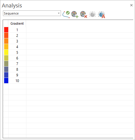
Identifies the start and end point of the entire machining, the cutting method (such as Zig-Zag, One-Way, etc.), and the cut order (that is, from inside to outside, or from outside to inside)
-
Color: used to select a specific color.
-
Gradient: a number representing the number of colors used.
-
Refresh: applies the last modification user made
-
Add: adds one color and automatically re-calculates the gradient colors
-
Remove: removes one color and automatically re-calculates the gradient colors
-
Auto Adjust: resets the colors and number of them to default.
Rotation Axis Value
The toolpath will be colorized after the tilt angle of the machines rotation axis. The coloring of the toolpath is done based on angle intervals.
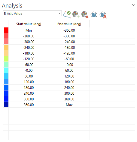
Identifies the rotation axis angle range being used, under which rotation angle a certain area is machined, and any limit overruns.
-
Color: used to select a specific color.
-
Start value (deg): represents the starting value in degrees for the interval that will have the specific color
-
End value (deg): represents the end value in degrees for the interval that will have a specific color
-
Refresh: applies the last modifications made by the user.
-
Add: adds one color and automatically recalculates the gradient colors
-
Remove: removes one color and automatically recalculates the gradient colors
-
Auto Adjust: resets the colors and number of them to default.
The number of decimals is controlled using Move List > Context Menu > Settings > Move list settings dialog.
-
Adjust: opens the Adjust Angle Scale dialog, which has the following options:
-
Minimum angle: the minimum colors interval value for the angle of the respective rotational axis.
-
Maximum angle: the maximum colors interval value for the angle of the respective rotational axis.
-
Reset to default: resets the minimum and maximum colors interval values for the rotational axis to default (which is -360 and 360, respectively).
-
Rotation Axis Value Change
The toolpath will be colorized after the tilt angle of one (A,B or C) of the machines rotation axis value changes. The coloring of the toolpath is done on angle intervals.
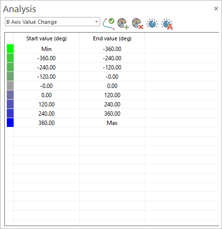
Identifies the rotation speed range being used, and under which rotation speed a certain area is machined. The rotation speed gives feed back where machine speed limits are reached and where you can expect stability issues of the process which influences the final surface quality.
-
Color: used to select a specific color.
-
Start value (deg): represents the starting value for the interval that will have the specific color
-
End value (deg): represents the end value for the interval that will have a specific color
-
Refresh: applies the last modifications made by the user.
-
Add: adds one color and automatically re-calculates the gradient colors.
-
Remove: removes one color and automatically re-calculates the gradient colors.
-
Auto Adjust: resets the colors and number of them to default.
The number of decimals is controlled using Move List > Context Menu > Settings > Move list settings dialog.
-
Adjust: opens the "Adjust Angle Change" window which has the following options:
-
Angle change: defines the maximum value of the angle of the respective rotational axis that needs to be rotated between two consecutive moves. Only strictly positive values smaller than 100000 degrees are allowed. The value is used to define the color intervals for the list of colors.
-
Reset to default: resets the value of the angle to default, which is 360.
-
Rotation Axis Reversal
The toolpath will be colorized after rotation axis reversals. So every time when the rotation axis changes the direction the toolpath segment will change the color.
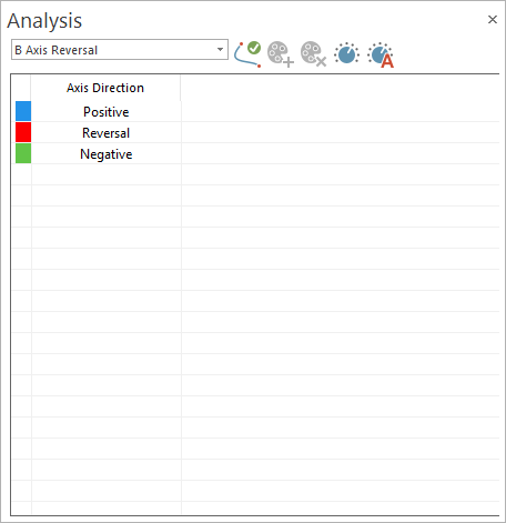
Used to identify the area where possible contouring errors have negative influence on the machining result, surface quality.
-
Color: used to select a specific color.
-
Axis Direction:
-
Positive;
-
Reversal;
-
Negative.
-
-
Refresh: applies the last modifications made by the user.
-
Auto Adjust: resets the colors and number of them to default.
-
Adjust: opens the "Rotary axis reversal threshold angle" window, which has the following options:
-
Rotary axis reversal threshold angle: the value of the angle change used to determine the switch between positive and negative direction of the axis.
-
Rotation Axis Speed
The toolpath will be colorized after the intervals for rotational axis speed.
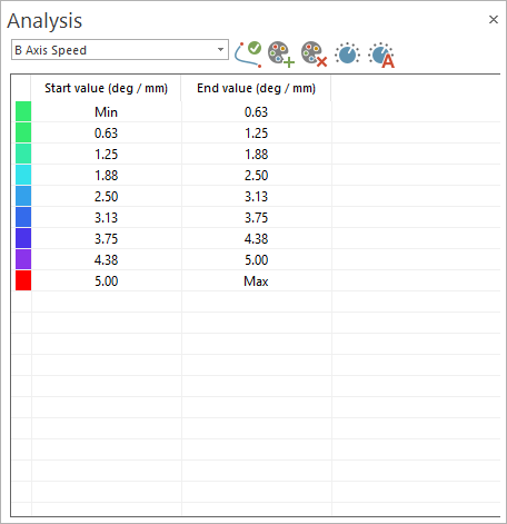
Identifies the rotation speed range being used, and under which rotation speed a certain area is machined. The rotation speed gives feedback where machine speed limits are reached and where you can expect stability issues of the process which influences the final surface quality.
-
Color: used to select a specific color.
-
Start value (deg / unit): determines the minimum number of degrees that the respective axis could move in a minute.
-
End value (deg / unit): determines the maximum number of degrees that the respective axis could move in a minute.
-
Refresh: applies the last modifications made by the user.
-
Add: adds one color and automatically re-calculates the gradient colors.
-
Remove: removes one color and automatically re-calculates the gradient colors.
-
Auto Adjust: resets the colors and number of them to default.
The number of decimals is controlled using Move List > Context Menu > Settings > Move list settings dialog.
-
Adjust: opens the "Adjust Angle Change" window, which has the following options:
-
Minimum angle: the minimum colors interval value for the angle of the respective rotational axis.
-
Maximum angle: the maximum colors interval value for the angle of the respective rotational axis.
-
Reset to default: resets the minimum and maximum colors interval values for the rotational axis to default (which is 0.625 and 5, respectively).
-
Rotational Axis Speed
The toolpath will be colorized after the tilt angle of both machines rotation axis value change.
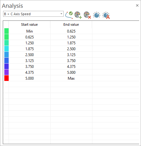
Identifies the rotation speed range being used, and under which rotation speed a certain area is machined. The rotation speed gives feed back where machine speed limits are reached and where you can expect stability issues of the process which influences the final surface quality.
-
Color: used to select a specific color.
-
Start value: the start value of the respective color interval of the tilt angle of both rotation axis.
-
End value: the end value of the respective color interval of the tilt angle of both rotation axis .
-
Refresh: applies the last modifications made by the user.
-
Add: adds one color and automatically recalculates the gradient colors.
-
Remove: removes one color and automatically recalculates the gradient colors.
-
Auto Adjust: resets the colors and number of them to default.
The number of decimals is controlled using Move List - Context Menu - Settings - Move list settings dialog.
-
Adjust: opens the Adjust Angle Change window, which has the following options:
-
Minimum angle: the minimum colors interval value for the angle of both the respective rotational axis.
-
Maximum angle: the maximum colors interval value for the angle of both the respective rotational axis.
-
Reset to default: resets the minimum and maximum colors interval values for both the rotational axis to default (which is 0.625 and 5, respectively).
-
Linear Axis Reversal
The toolpath will be colorized after linear axis reversals. So every time when the linear axis changes the direction the toolpath segment will change the color.
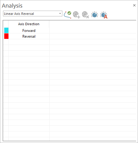
Used to identify the area where possible contouring errors have negative influence on the machining result, surface quality
-
Color: used to select a specific color.
-
Axis Direction:
-
Forward;
-
Reversal.
-
-
Refresh: applies the last modification made by the user.
-
Auto Adjust: resets the colors and number of them to default.
-
Adjust: opens the Linear axis reversal threshold angle window, which has the following options:
-
Linear axis reversal threshold angle: the value of the angle change used to determine the switch between forward and reversal direction of the linear axis. Only values within 90 - 180 degrees are allowed.
-
Orientation Change
The toolpath will be colorized after its orientation change angle between 2 segments. Used to identify the curvature of the toolpath.
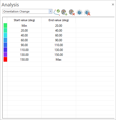
Find the areas where the toolpath is fluent and smooth or area where it is edgy where errors have negative influence on the machining result, surface quality.
-
Color: used to select a specific color.
-
Start value (deg): the start value of the colors interval.
-
End value (deg): the end value of the colors interval.
-
Refresh: applies the last modification made by the user.
-
Add: adds one color and automatically recalculates the gradient colors.
-
Remove: removes one color and automatically recalculates the gradient colors.
-
Auto Adjust: resets the colors and number of them to default.
The number of decimals is controlled using Move List > Context Menu > Settings > Move list settings dialog.
-
Adjust: opens the "Adjust Orientation Change" window, which has the following options:
-
Minimum angle: the minimum colors interval value for the angle between the two toolpath segments.
-
Maximum angle: the maximum colors interval value for the angle between the two toolpath segments.
-
Reset to default: resets the minimum and maximum colors interval values for the angles between two toolpath segments. (which is 20 and 150, respectively).
-
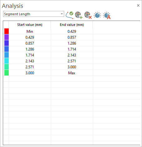
Segment Length
The toolpath will be colorized after the length of the segments. Used to identify the areas where you have long linear motions, usually in roughing toolpath or where the segments become very short, such as for finishing.
-
Color: used to select a specific color.
-
Start value (unit):
-
End value (unit):
-
Refresh: applies the last modification made by the user.
-
Add: adds one color and automatically recalculates the gradient colors.
-
Remove: removes one color and automatically recalculates the gradient colors.
-
Auto Adjust: resets the colors and number of them to default.
The number of decimals is controlled using Move List - Context Menu - Settings - Move list settings dialog.
-
Adjust: opens the Adjust Segment Length window, which has the following options:
-
Minimum Segment: the minimum colors interval value for the toolpath segments.
-
Maximum Segment: the minimum colors interval value for the toolpath segments.
-
Reset to default: resets the minimum and maximum colors interval values for the toolpath segments. (which is 0.429 and 3, respectively).
-
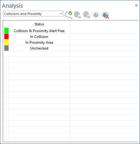
Collisions and Proximity
The toolpath will be colorized after collisions status. Provides a better overview of the toolpath segments that are in collision or not, toolpath sections that are not checked for collision and also see were the toolpaths segments and in close proximity to other machine elements.
-
Color: used to select a specific color.
-
Status:
-
Colllision & Proximity Alert Free: the toolpath is not yet checked.
-
In Collision: the toolpath is checked and collision free.
-
In Proximity Area: the tool is colliding with the geometry.
-
Unchecked: the tool is closer from geometry, in a proximity limit. This limit can be defined by the tool clearances or by a specific distance
-
-
Refresh: applies the last modifications made by the user.
-
Auto Adjust: resets the colors and number of them to default.
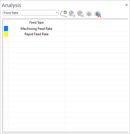
Feed Rate
The toolpath will be colorized after the feed rate.
-
Color: used to select a specific color.
-
Feed Type:
-
Machining Feed Rate: means that the toolpath has machining feed rate.
-
Rapid Feed Rate: means that the feed rate is rapid rate.
-
-
Refresh: applies the last modification made by the user.
-
Auto Adjust: resets the colors and number of them to default.
Height Change
The toolpath will be colorized after the orientation of the tool relative to the toolpath.
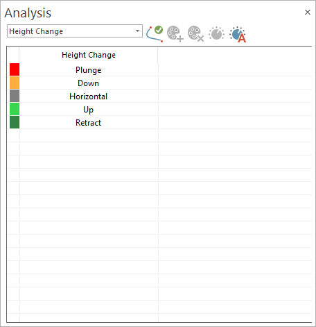
Identifies whether the tool is plunging into the part along its tool axis or with an angle, if the tool is been pulled or pushed, and if the tool is retracting from the part along its tool axis or with an angle.
-
Color: used to select a specific color.
-
Height Change:
-
Plunge: Plunge in tool axis direction
-
Down: Lag angle orientation of the tool (pushing)
-
Horizontal: Normal orientation
-
Up: Lead angle orientation of the tool (pulling)
-
Retract: Retracting along tool axis
-
-
Refresh: applies the last modification made by the user.
-
Auto Adjust: resets the colors and number of them to default.
Axis Pole
The toolpath will be colorized to determine if the 2 rotation axes of a 5-axis machine kinematic configuration are co-linear. The color scheme reaches from blue to red.
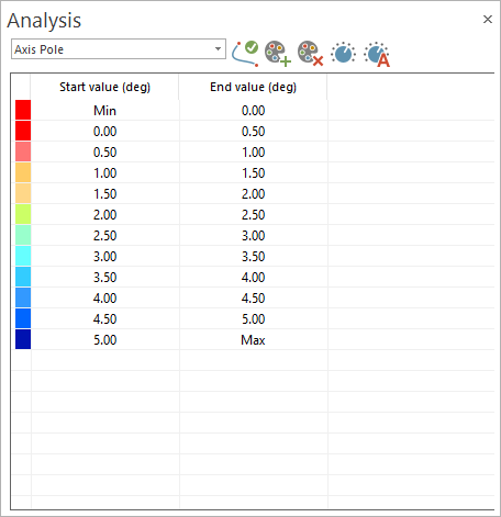
The more the axes get co-linear, the more the toolpath turns to red. Used to identify tool orientations that are near the pole.
-
Color: used to select a specific color.
-
Start value (deg): the start value angle for the interval in which the color is used. By changing this, it will automatically also change the "End value" from the previous interval.
-
End value (deg): the end value angle for the interval in which the color is used. By changing this, it will automatically also change the "Start value" from the next interval.
-
Refresh: applies the last modification made by the user.
-
Add: adds an interval below the selected one.
-
Remove: removes the selected interval.
-
Auto Adjust: auto adjusts the minimum and maximum angle values based on the work envelope of rotation axis from all operations, without changing the colors or number of intervals.
The number of decimals is controlled using Move List - Context Menu - Settings - Move list settings dialog.
-
Adjust: allows the user to set a custom interval for his entire analysis or rest to default everything and opens the "Adjust Axis Pole" dialog, which has the following options:
-
Minimum Angle: establishes the minimum angle value, the one that will be colored in red.
-
Maximum Angle: establishes the maximum angle value, the one that will be colored in blue.
-
Reset to default: resets the interval colors, the number of them and values to default.
-
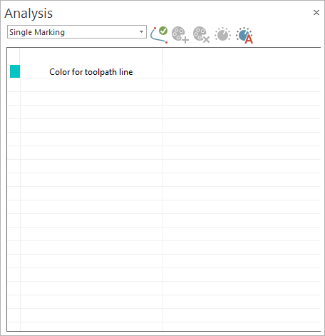
Single Marking
The machining toolpath will be colorized in a single color.
-
Color: used to select a specific color.
-
Color for toolpath line: represents the color for the entire toolpath.
-
Refresh: applies the last modification made by the user.
-
Auto Adjust: resets the toolpath color to default.